Download
1 / 26
290 likes | 343 Views
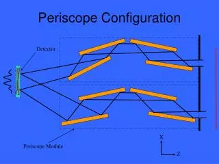
X. Z. Periscope Configuration. Detector. Periscope Module. 2, 10, or 30 cm. 30 cm. Mirror Parameters. Reflecting surface. TBD. Active area is 30cm long x 2, 10 or 30cm wide. Surface figure requirement: l /400 rms (at 633nm) -- Mounted Mirror mass must be minimized Geometry TBD. X.

E N D
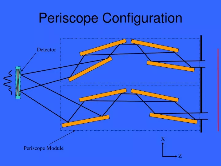
X Z Periscope Configuration Detector Periscope Module
2, 10, or 30 cm 30 cm Mirror Parameters Reflecting surface TBD • Active area is 30cm long x 2, 10 or 30cm wide. • Surface figure requirement: l/400 rms (at 633nm) --Mounted • Mirror mass must be minimized • Geometry TBD
X Z=LOS Yaw Roll Y Pitch Mirror Module Coordinate System Mirror Control: X – linear Roll about LOS Pitch LOS Fixed Mirrors Module Control: Yaw Pitch Roll about LOS To Detector
Mirror Geometry and Figure Mirror geometry must: • Meet the surface figure requirement • 1g release • Operating temperature range • Thermal gradient • Mount distortions • Have minimum mass • Accommodate mount and mechanisms • Survive launch and environment extremes
First Order Wavefront Error Budget Error Budget for /400 RMS Mirror Mount All values given in RMS wavefront error = 6328Å Thermal gradient .0011 Jitter .0006 Mount interface surface finish .0003 Mirror blank surface figure .0013 Stability .0013 Assembly (neglected) Surface distortion due to gravity .0004 Motion due to gravity (neglected) Manufacturing .0013 Test .0013 Alignment .0013 Reflective coating .0009 Bolt preload .0002 Adhesive strain .0002 Bulk temp (5°C) .0005 1g sag .0004 Total RMS error .0025
X Y Z Initial Geometries considered: • Rectangular, held from back • Various lightweighting patterns/pockets cut from back • Single Arch • Various thicknesses • Double arch over length on backside • Lightweighting pockets in back of main rib
First Order FEM results of different geometries for 1m long mirror
Wavefront analysis • Wavefront analysis not adequate: Zernike polynomials do not fit to long rectangular optical surface • Consider using LeGendre polynomials? • Good for cylindrical optic fits (used Chandra mirror analysis) • Orthogonal polynomials? Ref. Integrated Optomechanical Analysis Doyle, Genberg, Michels, p.61
Optical Tolerances • Goal: Good fringe clarity at the focal plane • Maintain phase information as it passes through each channel of the interferometer simultaneously • Analytical Analysis: • Limit OPD < l/10 • Raytrace Analysis: • Limit relative Strehl ratio > 80%
Analytical vs. RaytraceMirror Position Tolerances where l = 20Å, g =2°, m = 83cm, and L = 400km
MAXIM Pathfinder Parameters • Baseline = 2 m • Focal Length = 200 km • Mirror length = 30 cm • Graze angle = 2° • l = 10Å
MAXIM Pathfinder Position Tolerancesl=1nm, F=200km, D=2m, m=30cm, g=2deg, dh=1mm
Full MAXIM Parameters • Baseline = 1km • Focal Length = 20,000 km • Mirror length = 30 cm • Graze angle = 1° • l = 10Å
X-direction Sensitivity F X D Z y Allowable Mirror Motion: ± 1.7nm Allowable Periscope Motion: ± 4mm
Y-direction Sensitivity X Z=LOS Y Allowable Mirror Motion: ± 0.3mm Allowable Periscope Motion: ± 0.5mm
X Z Z-direction Sensitivity F D y Allowable Mirror Motion: ± 94.7nm Allowable Periscope Motion: ± 0.32m
Y Z Allowable Mirror Motion: ± 6.9arcmin X-rotation “yaw” Sensitivity msin(g) m Allowable Periscope Motion: ± 7.8 arcmin
X Z Allowable Periscope Motion: ± 10 arcsec Y-rotation “pitch” Sensitivity F y D Allowable Mirror Motion: ± 2.3 marcsec
Allowable Periscope Motion: ± 18.5 arcsec Z-rotation “roll” Sensitivity LOS X Z=LOS Roll Y Allowable Mirror Motion: ± 0.13 arcsec To Detector
MAXIM Position Tolerancesl=1nm, F=20,000km, D=1km, m=30cm, g=1deg, dh=1mm
ISAL Raytrace Position Tolerancesl=1nm, F=200km, D=4m, m=30cm, g=1deg, dh=1mm
Move one mirror pair wrt other mirror pair -d +d Pathlength is self-correcting
Move one mirror in Z-direction +d dcos2q 2q -d dsinq
Trade Studies • Three grating sizes: • 2cm, 10cm, and 30cm wide x 30 cm long • Optimize graze angle vs. mass • Lower graze angle can loosen some tolerances • Lower graze angle will reduce throughput or increase mass