Download

1 / 28
280 likes | 394 Views
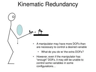
KINEMATIC CHAINS AND ROBOTS (III). Kinematic Chains and Robots III. Many robots can be viewed as an open kinematic chains. This lecture continues the discussion on the analysis of kinematic analysis robots. After this lecture, the student should be able to:

E N D
KINEMATIC CHAINS AND ROBOTS (III)
Kinematic Chains and Robots III • Many robots can be viewed as an open kinematic chains. This lecture continues the discussion on the analysis of kinematic analysis robots. • After this lecture, the student should be able to: • Solve problems of kinematic analysis using transformation matrices
Link (0): Base The base is chosen to act as link (0)
Link (1) Link (0): Base The next link coupled to the base is link (1)
Link (2) Link (1) The next link coupled to link (1) is link (2)
Link (3): Gripper Link (2) The next link coupled to link (2) is link (3)
Link (2) Link (3): Gripper Link (1) Summary of Link Assignment Link (0): Base
Revolute joint <1> Link (1) Link (0): Base Joint <1> is between link (0) and link (1)
Revolute joint <2> Link (2) Link (1) Joint <2> is between link (1) and link (2)
Revolute joint <3> Link (2) Link (3): Gripper Joint <3> is between link (2) and link (3)
Link (2) Revolute joint <2> Revolute joint <3> Link (3): Gripper Link (1) Revolute joint <1> Summary of Links and Joints Assignment Link (0): Base
Y0 X0 Define the base or reference frame {0} with origin at joint <1>. Notice that Z0 is pointing towards you and X0, Y0, & Z0 form a right hand frame of reference. Note that this base frame is used to describe the global position of the end-effector (or gripper).
X1 Y1 Revolute joint <2> Revolute joint <1> The intersection between the common perpendicular of axes through <2> and <1> with <1> is the origin of frame {1}. X1 points along the common perpendicular from <1> to <2>. Z1 is pointing towards you and defines the axis of rotation of joint <1>. X1, Y1, & Z1 form a right hand frame of reference.
1 X1 Y1 Remember that Z1 is pointing towards you and defines the axis of rotation of joint <1>, i.e. 1 is positive if link (1) rotates counter-clockwise
Y2 X2 Revolute joint <2> Revolute joint <3> The intersection between the common perpendicular of axes through <3> and <2> with <2> is the origin of frame {2}. X2 points along the common perpendicular from <2> to <3>. Z2 is pointing towards you and defines the axis of rotation of joint <2>. X2, Y2, & Z2 form a right hand frame of reference.
2 Y2 X2 Remember that Z2 is pointing towards you and defines the axis of rotation of joint <2>, i.e. 2 is positive if link (2) rotates counter-clockwise
Y3 X3 Revolute joint <3> Choose the origin of frame {3} on axis <3>. Z3 is pointing towards you and defines the axis of rotation of joint <3>. We have selected X3 to point along the length of link <3>. X3, Y3, & Z3 form a right hand frame of reference.
3 Y3 X3 Remember that Z3 is pointing towards you and defines the axis of rotation of joint <3>, i.e. 3 is positive if link (3) rotates counter-clockwise
Y2 X2 Y3 X3 X1, Y0 Y1 X0 Summary of Frame-assignment
Tabulation of D-H parameters A2 Y2 X2 Y3 X3 A1 Y0 ,X1 Y1 X0 We shall let the above configuration to be called the home position for the robot. A1 and A2 are the lengths of links (1) & (2) respectively
Y0 ,X1 Y1 X0 0 = (angle from Z0 to Z1 measured along X0) = 0° a0 = (distance from Z0 to Z1 measured along X0) = 0 d1 = (distance from X0 to X1 measured along Z1)= 0 1 = (angle from X0 to X1 measured along Z1) 1 = 90° (at home position) but 1 can change as the arm moves
Y2 X2 A1 X1 Y1 1 = (angle from Z1 to Z2 measured along X1) = 0° a1 = (distance from Z1 to Z2 measured along X1) = A1 d2 = (distance from X1 to X2 measured along Z2) = 0 2 = (angle from X1 to X2 measured along Z2) 2 = -90° (at home position) but 2 can change as the arm moves
A2 Y2 X2 Y3 X3 2 = (angle from Z2 to Z3 measured along X2) = 0° a2 = (distance from Z2 to Z3measured along X2) = A2 d3 = (distance from X2 to X3 measured along Z3) = 0 3 = (angle from X2 to X3 measured along Z3) 3= -90° (at home position) but 3 can change as the arm moves
Summary • Many robots can be viewed as an open kinematic chains. This lecture continues the discussion on the analysis of kinematic analysis robots. • The following were covered: • Kinematic analysis using transformation matrices