Download

1 / 53
530 likes | 748 Views
Simultaneous Removal of SO 2 and CO 2 From Flue Gases at Large Coal-Fired Stationary Sources. Chemical Engineering Department, Yale University, New Haven, CT 06520 AQSim, Inc., Glen Ridge, NJ 07028. Y. F. Khalil (1) and AJ Gerbino (2). OLI’s 24 th User Conference

E N D
Simultaneous Removal of SO2 and CO2 From Flue Gases at Large Coal-Fired Stationary Sources • Chemical Engineering Department, Yale University, New Haven, CT 06520 • AQSim, Inc., Glen Ridge, NJ 07028 Y. F. Khalil(1) and AJ Gerbino(2) OLI’s 24th User Conference Hyatt Hotel, Morristown, NJ October 23 – 24, 2007
Presentation Outline • Motivation for developing alternative technologies for CO2 capture: - U.S. GCCI • Integrated control technologies (ICTs) • Technical and economic barriers of CO2 capture using MEA • Research objectives • Research apporach for modeling CO2 and SO2 capture using: - OLIs’ ESP - ICEM (DOE model) • Results and discussion: IECM and ESP • Summary • Roadmap for future work
Motivation #1: The U.S. Global Climate Change Initiative (GCCI) • GCCI is one of the primary drivers for CO2 emission reduction. • Between 2002 and 2012, this initiative targets 18% reduction in the greenhouse gases (GHGs) intensity. • A second goal of this initiative is to provide a portfolio of commercially-ready CO2 removal technologies for 2012 assessment. 3
Motivation #2: Integrated Control Technologies (ICTs) • More cost effective compared to single-effect technologies • Less footprint and, hence, easier to retrofit • Possibility of sharing some unit operations • Possibility of shared raw materials • Example: simultaneous removal of CO2 and SO2
Motivation #3: Monoethanolamine (MEA) Scrubber for CO2 Capture • MEA scrubbing is the conventional technology for CO2 capture from flue gases • Unfortunately this technology is energy-intensive -- a significant amount of energy is required for recovering the MEA solvent: 67% of the MEA plant operating cost is attributed to steam requirements for solvent regeneration and 15% of the cost is for MEA makeup. • MEA is corrosive and requires adding corrosion inhibitors • For a 500 MWth coal-fired plant, MEA makeup ~ 22.7 tons/hr • MEA recirculated ~ 6,599 tons/hr Some CO2 remains in the regenerated MEA MEA makeup • Additional drawback of MEA technology: • Low CO2 loading, i.e., grams of CO2 absorbed per gram of absorbent. MEA HEX
Total Energy: 3.41 MBtu/ton CO2 • Slightly compress the feed gas to 1.2 bar • 0.15 MBtu/ton CO2 • Desorb CO2 in the stripper • 2.9 MBtu/ton CO2 • Compress the CO2 off-gas to 100 bar • 2 stages at 0.18 MBtu/ton CO2 each Source: J. L. Anthoney, Dept. of Chem. Eng, Kansas State U.
Cost of Raw Materials Costs are based on 2005 dollars (as provided by the IECM program) • 5.1 kg MEA (pure solvent) per 1 kg CO2 removed • From reaction stoicheometry: ~ 1.16 kg Ca(OH)2 per 1 kg SO2 removed ~ 1.68 kg Ca(OH)2 per 1 kg CO2 removed
Research Objectives • Model the simultaneous removal of SO2 and CO2 gases by chemi-sorption in a slurry of hydrated lime [Ca(OH)2]. • Benchmark the performance/effectiveness of this proposed technology with: • MEA scrubbing approach for CO2 removal • Wet flue gas desulfurization (FGD) for SO2 removal • These separate-effect technologies (MEA and FGD) are typically connected in series in a fossil-fired power plant 8
Research Approach Three-Fold Approach: • 1. Use OLI’s Environmental Simulation Program (ESP, v-7.0-55) to model the simultaneous removal of SO2 and CO2 gases by scrubbing into a slurry of hydrated lime [Ca(OH)2]. • Three hypothetical flue gas compositions are to be evaluated : CO2 concentrations of 3%, 14%, and 25%; representative of exhaust streams of a NG-fired power plant, coal-fired power plant, and a cement production plant, respectively. • - Only the coal-fired plant (11 – 15% CO2) is discussed in this presentation • Concentration of SO2 in the flue gas is assumed to be 2000 ppm 9
Research Approach Three-Fold Approach (cont’d): • 1. Use the OLI’s Environmental Simulation Program (ESP, v-7.0-55) to model the simultaneous removal of SO2 and CO2 gases by scrubbing into a slurry of hydrated lime [Ca(OH)2]. • Flue gas flow rate was kept constant at ~ 1.6x10⁶ acfm (~ 2.7x10⁶ m3/hr); such flow rate is typical of a 500 MWth coal fired power plant. • The proposed process includes a SO2 scrubber, a CO2 scrubber, a calciner, a lime slaking reactor, and a few auxiliary unit operations such as heat exchangers, filters and dryers. 10
Research Approach Three-Fold Approach (cont’d): • Use the Integrated Environmental Control Model (IECM) • software to predict the performance of a coal-fired plant that uses MEA scrubbing for CO2 capture and wet FGD unit for SO2 removal • IECM software has been developed by the Center for Energy and Environmental Studies, Carnegie Mellon University for DOE in 2007 (Current Version: 5.21; February 2, 2007) • Compare ESP predictions with IECM predictions for CO2 and SO2 removal 11
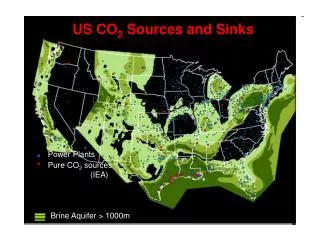
Importance of the Proposed Integrated Technology The proposed integrated technology for simultaneous removal of CO2 and SO2 could be of interest to many industrial facilities including: • Fossil-fuel-based power generation stations; which contribute about 30% of the World’s CO2 emissions • Coal-fired gasification combined cycle (IGCC) turbines • Cement production plants • Petrochemical plants 12
Chemical Reactions for CO2 Removal CO2 Gas Absorption Reaction (carbonation reaction): CO2 (g) + Ca(OH)2 CaCO3 + H2O Ho298K -113 kJ/mole Calcination Reaction: CaCO3 CaO + CO2 (g) Ho298K 178 kJ/mole Lime Slaking Reaction: CaO + H2O Ca(OH)2 Ho298K -65 kJ/mole H2O Lime Slaker Ca(OH)2 CaO CO2 in flue gas CO2 Carbonator Calciner CaCO3 13
Carbonator: Exothermic Reaction CO2 (g) + Ca(OH)2 CaCO3 + H2O G, kJ/mole GR at 298oK = -72.643kJ/mole HR, kJ/mole HR at 298oK = -113.03 kJ/mole GR ad HR are calculated by HSC software 15
Calciner: Endothermic Reaction CaCO3 (s) CaO (s) + CO2 (g) GR at 1198oK = -5.528kJ/mole GR at 1273oK = -16.169 kJ/mole Typical Calciner Temperature Range 1220oK – 1420oK HR at 1198oK = 164.949kJ/mole HR at 1273oK = 163.207 kJ/mole G, kJ/mole HR, kJ/mole 16 GR ad HR are calculated by HSC software
Lime Slaker: Exothermic Reaction CaO(s) + H2O Ca(OH)2 GR at 298oK = -57.804kJ/mole G, kJ/mole HR at 298oK = -65.145kJ/mole HR, kJ/mole 17 GR ad HR are calculated by HSC software
Chemical Reactions for SO2 Removal SO2 Gas Absorption Reaction: SO2 (g) + Ca(OH)2 CaSO3 (s) + H2O Ho298K -163 kJ/mole Forced Oxidation of CaSO3 to CaSO4: CaSO3 (s) + 1/2O2 (g) CaSO4 (s) Ho298K -556 kJ/mole CaSO3 or CaSO4 Makeup CaO to compensate for Ca lost in CaSO3 or CaSO4 SO2 in flue gas Lime Slaker Ca(OH)2 H2O Lime Slaker Ca(OH)2 CaO CO2 in flue gas CO2 Carbonator Calciner CaCO3 18 18
SO2 Absorption: Exothermic Reaction G, kJ/mole HR, kJ/mole GR at 298oK = -114.736kJ/mole HR at 298oK = -162.509kJ/mole GR ad HR are calculated by HSC software 19
Forced Oxidation of CaSO3: Exothermic Reaction G, kJ/mole HR, kJ/mole HR at 298oK = -556.469kJ/mole GR at 298oK = -498.504kJ/mole GR ad HR are calculated by HSC software 20
Chemical Reactions for Co-Production of SynGas Co-Production of Lime and Syngas: CaCO3 + CH4 (g) CaO + 2CO (g) + 2H2 (g) Ho 298 K 426 kJ/mole • Typical Calciner Temperature Range 1220oK – 1420oK • Hence, co-production of Syngas can take place within the calciner temperature range 21
SynGas Production: Endothermic Reaction G, kJ/mole HR, kJ/mole GR ad HR are calculated by HSC software 22
Mitigation of Operating Risks of the Calciner • Lime Sintering (decrease in surface area and pore size of CaO) • Reducing the operating temperature of the calciner results in less sintering of the produced calcium oxide and, hence, more reactive lime (CaO) in the lime slaker. • Cost of CaO Makeup Due to Loss of Reactivity • Because calcium is used continuously in a cyclical manner, sintering and corresponding reduction in reactivity is a cumulative process that may require periodic makeup of calcium oxide. If calcium can be recycled say 500 times, then it may easily be considered to be cost effective. 23
Simulation of CO2 Removal Using DOE/IECM User defined HR = -84.6 kJ/mole CO2 HR (30 wt% MEA in water) = -84.6 kJ/mole CO2 & Mass of MEA (30 wt%) to absorb 1 kg CO2 = 17 kg MEA solution
Simulation of SO2 Removal Using DOE/IECM User defined
Simulation Results of MEA-Based Technology for CO2 Removal Using the Integrated Environmental Control Module (IECM) 27
CO2 Coal-Fired Boiler Absorber • Remove heat of chemisorption • Cool lean regenerated MEA solvent by removing sensible heat Stripper • Heat the rich MEA solvent by extracting sensible heat from the lean MEA solvent • Supply heat of desorption using steam in the reboiler Possible Power Plant Capture Add-ons • Cool flue gas to absorber conditions (25oC) • Compress flue gas to overcome pressure drop in Absorber • Post compression of CO2 to desired product pressure 28
31 CO2 removal = (2.667E6 tons/yr) / 6575 hrs/yr ~ 406 tons/hr for a 500 MWth coal-fired plant
CO2 (mole%) in input flue gas = 2.048E4 lb-mole/hr / 1.706E5 lb-mole/hr ~ 12% CO2 removal efficiency = 90% (user defined) and CO2 escape with flue gas = 10% 32
33 MEA scrubber plant cost about $281M / $700M ~ 37% of the 500 MWth plant cost
Simulation Results of Wet-FGD Technology for SO2 Removal Using the Integrated Environmental Control Module (IECM) 36


![[SO 2 + H 2 O H 2 SO 3 ] SO 3 + H 2 O H 2 SO 4 CO 2 +H 2 O H 2 CO 3](https://cdn2.slideserve.com/4275035/slide1-dt.jpg)