Download
1 / 44
460 likes | 721 Views
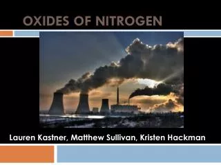
Control of Oxides of Nitrogen from Stationary Sources. Oxides of Nitrogen. The gaseous oxides of nitrogen include: N2O:nitrous oxide NO:nitric oxide (free radical) N2O3: nitrogen trioxide NO2:Nitrogen dioxide (free radical) N2O5:nitrogen pentoxide An unstable form NO3 also exists.

E N D
Oxides of Nitrogen • The gaseous oxides of nitrogen include: • N2O:nitrous oxide • NO:nitric oxide (free radical) • N2O3: nitrogen trioxide • NO2:Nitrogen dioxide (free radical) • N2O5:nitrogen pentoxide An unstable form NO3 also exists. Only N2O,NO, and NO2 present in the atmosphere in significant concentrations
NO and NO2 (NOx) • NO is a colorless gas with average ambient concentration of 0.5 ppm • No adverse health effect at this concentration but it is a precursor to the formation of NO2 and active compound in photochemical smog formation • NO2 is a reddish brown gas. A concentration of 1 ppm can be detected by the eye. Adverse health effect is primarily associated with the pulmonary problems.On an annual basis air ambient air level standart is 0.05 ppm (100 ug/m3)
Sources and Concentrations of NOx • Over 90% of all man-made nitrogen oxides entering the atmosphere are from combustion sources • For the US, 50% is from mobile sources • For Turkey ambient NOx concentration is around xx • At an emission source the concentration of oxided of nitrogen is much higher than ambient values • For example the NOx concentration in the flue gas from the steam boiler of a power plant may reach 500 to 1000ppm • From such combustion processes the NOx is the exhaust stack gas would be 90% or more NO and the rest NO2
NOx Control • 1. Control over the reaction that produces the pollutant • 2. Remove NOx after it is formed
NOx FormationBasic Chemistry,Thermodynamics and Kinetics of the Formation Reactions • There are two sources of N that contribute to the formation of oxides of nitrogen • 1. Fuel N (Coal and fuel oil composition, note that no N in natural gas)(Fuel NOx) • 2. Air N (78% of air is N)(Thermal NOx)
Thermodynamics of Thermal NOx Formation • It is essential to understand the thermodynamics and kinetic of nitrogen-oxygen reactions, especially at high temperatures • NOx formation mechanism was first proposed by Zeldovich (1946): • N2+O⇋NO + N (1) • N+O2⇋NO +O(2) • N+OH⇋NO +H(3) Reaction 1 and 2 are the most important reactions in the model.
Thermodynamics of Thermal NOx Formation • Let’s first consider only the NO and NO2 formation equilibrium reactions: • N2+O2⇋2NO (4) • NO+1/2O2⇋NO2 (5)
Predicted Equilibrium Concentrations 1. At flue gas exit T (420-590 K), expect to observe very low NOx (<1 ppm) and primarily NOx in the form NO2 1. At flame zone T (1850-3500 K), expect to observe very high NOx (up to 10000 ppm) and primarily NOx in the form NO
Predicted Equilibrium Concentrations 1. At flue gas exit T (420-590 K), expect to observe very low NOx (<1 ppm) and primarily NOx in the form NO2 • At actual furnaces however typical flue gas consists of 300-1200 ppm NOx and mostly (90-95%) in NO form • So there must be other factors other than equilibrium to explain this:
Kinetics of Nitric Oxide Formation in Combustion Process • The rate of NO formation is the major factor influencing NOx concentrations • Considering reactions 1 to 3, the rate expression can be written: • rNO= k+1[N2][O]-k-1[NO][N]+k+2[O2][N] -k-2[NO][O]+k+3[N][OH]-k-3[NO][H] • rN= k+1[N2][O]-k-1[NO][N]-k+2[O2][N] -k-2[NO][O]-k+3[N][OH]+k-3[NO][H]
Rate Constants k+1 k-1 k+2 k-2 k+3 k-3 T is in degrees Kelvin
Kinetics of Nitric Oxide Formation in Combustion Process • N atoms are much more reactive than NO, we can assume quasi steady state for N and an expression for [N]ss can be obtained: • [N]ss= k+1[N2][O]+k-2[NO][O]+k-3[NO][H]/ k-1[NO]+k+2[O2]+k+3[OH] And substituting this into rate equation for NO • rNO= k+1[N2][O]-k-2[NO][O]-k-3[NO][H]+( -k-1[NO]+k+2[O2]+k+3[OH])[N]ss
Kinetics of Nitric Oxide Formation in Combustion Process The interesting thing about above rate equation is that the initial rate of formation of NO (when NO concentrations are small) is just equal to twice that of reaction 1. That is: • rNO= k+1[N2][O]-k-2[NO][O]-k-3[NO][H]+( -k-1[NO]+k+2[O2]+k+3[OH])[N]ss N2+O⇋NO + N (1) rNOinitial= 2k+1[N2][O]
Example 16.2 • Given a HC flame at 1870 C where the mole fractions of N2 gas and O atoms are 0.75 and 9.5(10)-4 respectively, • a) calculate the initial rate of NO formation (in mole(m3-s) • b) if this rate holds constant for 0.03 seconds, calculate the concentration in ppm of NO in the gases leaving the flame zone
Solution • a) at T = 1870 C = 2143 K, k+1=1.8(10)8e-38,370/2143=3.015 m3/mol-s Assuming P= 1atm, the molar density of the gases: [N2]=0.75x5.686=4.26 mol/m3 [O]=9.5(19)-4x5.686=0.0054 mol/m3 rNOinitial= 2k+1[N2][O]=2(3.015)(4.26)(0.0054) =0.1388 mol/m3-s
Solution • b) If this inital rate holds for 0.03 seconds then [NO]=0.1388(0.03)=4.16(10)-3 mol/m3
Research on NOx Formation • Experimental results in various studies showed that NO concentrations in the flame zone are significantly higher than could have been formed by the Zeldovich mechanism • This may be due to “prompt” NO formation • Prompt NO: NO formed in the first five milliseconds (40-100 ppm)
Research on NOx Formation • MacKinnon worked with heated N2,O2, Ar samples • NO concentrations increased rapidly with time up to about 4-5 seconds, after no further increases observed
Research on NOx Formation • MacKinnon developed a model predicts the NO concentration (in ppm) as a function of temperature (in K), N and O concentrations, and time (in s)
NOx Formation from Fuel Nitrogen • When a fuel contains organically bound N, the contribution of the fuel bound N to the total NOx production is significant
Strategies for Combustion Modification • Reduce peak temperatures of the flame zone • Reduce gas residence time in the flame zone Aerosol & Particulate Research Lab
Modification of Operating Conditions • Off-Stoichiometric Combustion/Staged combustion: combusting the fuel in two or more steps. Fuel rich then fuel lean. • Flue gas recirculation: reroute some of the flue gas back to the furnace; lower O2 and allow NOx to proceed the “frozen” reactions • Water injection: reduce flame temperature; energy penalty http://en.wikipedia.org/wiki/Staged_combustion_cycle_(rocket) Aerosol & Particulate Research Lab
Gas reburning: injection of natural gas into the boiler above the main burner to create a fuel-rich reburn zone; hydrocarbon radicals react with NOx to reduce NOx to N2. Aerosol & Particulate Research Lab http://www.lanl.gov/projects/cctc/factsheets/eerco/gasreburndemo.html
Low-NOx burner: inhibit NOx formation by controlling the mixing of fuel and air; lean excess air and off-stoichiometric combustion Avoid Peak Temperature Aerosol & Particulate Research Lab
Flue Gas Treatment • Selective Catalytic Reduction (SCR) Temperature ~ 300 - 400 oC Q: Why is it called “selective”? Also good for Hg emission control!!! But it creates SO3. • Selective Noncatalytic Reduction (SNR) Temperature ~ 800 - 1000 oC Above 1000 oC Aerosol & Particulate Research Lab
SCR • Removal efficiency is over 90% • Expenses from use of catalyst • High operation and capital cost • Large area requirement • Requires temperature control for optiumum reduction
SNCR • No catalyst cost • High temperatures (850-1100) • Low removal efficiency ( %30-%66 less than SCR)
Other Control Methods • Absorption • Adsorption • Biological
Biological Control Technologies Under aerobic conditions, nitrification and chemical oxidation leads to NOx oxidation to nitrate. İlk denemelerde, yüksek O2 konsantrasyonlu aerobik şartlarda (>%17 Oksijen) NO giderimi toluenle muamele edilmiş silika pelet dolgulu bir biyofiltrede %97 mertebesinde başarılmıştır
Biological Control Technologies Anoksik koşullarda ise NOx denitrifikasyon prosesi yüksek bir verimle azot gazına indirgenmektedir. Toprak kompostu içeren laboratuar ölçekli bir biyofiltre çalışmasında NO2 için %100’e yaklaşan bir giderim verimi elde edilmiştir. (Okuno et. al, 2000). Tüm bunlar BiyoDeNox teknolojilerinin NOx kontrolü için gelecekte de artan oranlarda kullanılacağını göstermektedir.
Biological Control Technologies BioDeNOx Process
BioDeNOx Process • First nitrosyl complex was formed by the reactions 1 and 2: • NO (g) NO (aq) (1) • NO (aq) + Fe(II)EDTA2- > Fe(II)EDTA − NO2- (2)
BioDeNOx Process • To be able to regenarate the absorption liquid, formed Fe(III)EDTA- needs to be reduced to Fe(II)EDTA2- by the m/o • Regeneration of Fe(II)EDTA2- is essential for the system NO removal performance: • 12 Fe(III)EDTA- + C2H5OH + 3 H2O 12 Fe(II)EDTA2- + 2 CO2 + 12 H+
Jet-Loop Biyoreaktör • JetLoopreaktörlerdesistemiçindedrafttüpünepüskürtülengazreaktörüterketmedenöncedrafttüpüniçerisindebirkaçkezdeviryapmaktadır. • Devirsayısı ve jetakımındankaynaklanandahaküçükçaplıgazoluşumuNO gazınınortamabirkelatilaveetmeksizindahafazlaçözünmesini sağlamaktadır. İTÜ XIII. Endüstriyel Kirlenme Kontrolü Sempozyumu
Pilot Tesis • Toplam hacim 20 L, Çamur yaşı 50 gün, 1. Su girişi 2. Hava/gaz girişi 3. Hava/gaz çıkışı 4. JetLoop biyoreaktör 5. Su boşaltma vanası 6. Soğutucu 7. Su debimetresi 8. ÇO, Redox, pH, Sıcaklık sensörleri haznesi 9. Pompa 10. Besleme girişi 11. MBR sistemi, V: vana) İTÜ XIII. Endüstriyel Kirlenme Kontrolü Sempozyumu
Pilot Tesis İTÜ XIII. Endüstriyel Kirlenme Kontrolü Sempozyumu
Pilot Tesis İşletme Sonuçları İTÜ XIII. Endüstriyel Kirlenme Kontrolü Sempozyumu