Download
1 / 10
150 likes | 1.05k Views
Piezoresistive Sensors. EE485A Lecture Oct. 6, 2009. Piezoresistivity. Resistivity dependent on strain True for most semiconductors, including Si Also used to describe metal resistors where resistance change is geometry-driven (strain gauges)

E N D
Piezoresistive Sensors EE485A Lecture Oct. 6, 2009
Piezoresistivity • Resistivity dependent on strain • True for most semiconductors, including Si • Also used to describe metal resistors where resistance change is geometry-driven (strain gauges) • Characterized by Gauge Factor, G (s = strain, R = resistance) • Longitudinal and transverse strains often present at same time and could have different gauge factors. General expression for resistance change:
Exercise • A silicon resistor has resistivity 11.7 W-cm, and dimensions given by L = 20 um, W = 1 um, t = 0.5 um. Its longitudinal gauge factor is given by 120.6 • What is the resistance value for the resistor at rest? • What is the resistance change when the resistor undergoes a strain of 0.1%?
Piezoresistive Materials • Metal strain gauges typically exhibit gauge factors in range of 0.8 to 3 • G for single crystal silicon is orientation dependent and doping dependent but can range from 1 to 150. • G for polycrystalline silicon is not orientation dependent (and much smaller than for SCS), but is still doping dependent. • Peaks at -24 for n-type silicon doped to 3 x 1019 cm-3 • Peaks at 30 for p-type silicon doped to 1019 cm-3
Stress in Flexural Cantilevers A B E Fixed End C Free End t D W L Under Longitudinal Stress: A B E C F D Same strain seen at all points so piezoresistor location doesn’t matter s = F/A = F/(Wt) s = s/E
Stress in Flexural Cantilevers, cont. F Under Transverse Stress: A B E C D Maximum tensile stress (and strain) occur at points A, B, C. Compressive stress/strain occurs at D. E would be a poor choice for piezoresistor location) smax = FLt/(2I) s = FLt/(2EI) Effective designs Ineffective designs
Exercise Ftransverse • A silicon resistor is located at the base of a cantilever with resistivity 11.7 W-cm, and dimensions given by L = 100 um, W = 1 um, t = 0.5 um, and the material has a gauge factor given by 120.6 (same as previous example). The cantilever dimensions are given by length = 200 um, W = 20 um and t = 5 um. If a longitudinal force of 100 uN is applied to the end of the beam, what will be the resistance change? • Repeat if the force is transverse (applied at the tip) Flongitudinal
Translating resistance change into voltage • Simple voltage divider: • Wheatstone bridge: • Compared in homework
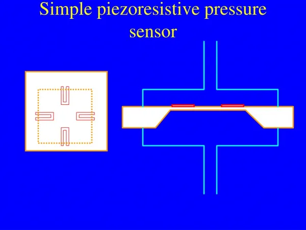
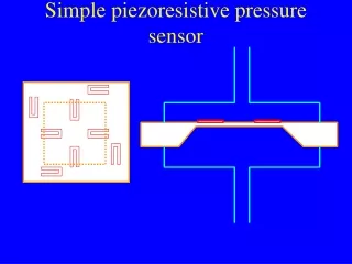
Stress in membranes • Maximum stress occurs at edges • Maximum stress of opposite sign occurs at center • For governing equations see sect. 6.3 in text • Typical piezoresistor configuration for pressure sensor:
Case Studies • See pp. 224-239 in text • Class exercise