Download
1 / 71
750 likes | 889 Views
Network Layer: Part I. Network Layer and IP Protocol! Part I: Network Layer Functions and Service Models Network Layer Functions IP Addressing Network Service Models: Virtual Circuit vs. Datagram IP Forwarding and IP Protocol IP Datagram Forwarding Model

E N D
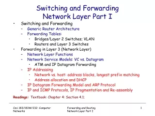
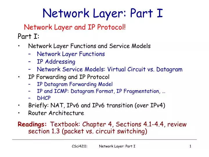
Network Layer: Part I Network Layer and IP Protocol! Part I: • Network Layer Functions and Service Models • Network Layer Functions • IP Addressing • Network Service Models: Virtual Circuit vs. Datagram • IP Forwarding and IP Protocol • IP Datagram Forwarding Model • IP and ICMP: Datagram Format, IP Fragmentation, … • DHCP • Briefly: NAT, IPv6 and IPv6 transition (over IPv4) • Router Architecture Readings: Textbook: Chapter 4, Sections 4.1-4.4, review section 1.3 (packet vs. circuit switching) CSci4211: Network Layer: Part I
network data link physical network data link physical network data link physical network data link physical network data link physical network data link physical network data link physical network data link physical application transport network data link physical application transport network data link physical What Does Network Layer Do? • End-to-end deliver packet from sending to receiving hosts, “hop-by-hop” thru network • A network-wide concern! • Involves every router, host in the network • Compare: • Transport layer • between two end hosts • Data link layer • over a physical link directly connecting two (or more) physically hosts CSci4211: Network Layer: Part I
transport segment from sending to receiving host on sending side encapsulates segments into datagrams on rcving side, delivers segments to transport layer network layer protocols in every host, router Router examines header fields in all IP datagrams passing through it network data link physical network data link physical network data link physical network data link physical network data link physical network data link physical network data link physical network data link physical application transport network data link physical application transport network data link physical Network layer CSci4211: Network Layer: Part I
Network Layer Functions • Addressing • Globally unique address for each routable device • Logical address, unlike MAC address (as you’ll see later) • Assigned by network operator • Need to map to MAC address (as you’ll see later) • Routing: building a “map” of network • Which path to use to forward packets from src to dest • Forwarding: delivery of packets hop by hop • From input port to appropriate output port in a router Routing and forwarding depend on network service models: datagram vs. virtual circuit CSci4211: Network Layer: Part I
Two Key Network-Layer Functions • analogy: • routing: process of planning trip from source to dest • forwarding: process of getting through single interchange • forwarding: move packets from router’s input to appropriate router output • routing: determine route taken by packets from source to dest. • routing algorithms CSci4211: Network Layer: Part I
Globally unique (for “public” IP addresses) IP address: 32-bit identifier for host, router interface Interface: connection between host/router and physical link router’s typically have multiple interfaces host may have multiple interfaces IP addresses associated with each interface Dot notation (for ease of human reading) 223.1.1.1 = 11011111 00000001 00000001 00000001 223 1 1 1 IP Addressing: Basics CSci4211: Network Layer: Part I
Two-level hierarchy network part (high order bits) host part (low order bits) What’s a network ? (from IP address perspective) device interfaces with same network part of IP address can physically reach each other without intervening router 223.1.1.2 223.1.1.1 223.1.1.4 223.1.1.3 223.1.7.0 223.1.9.2 223.1.9.1 223.1.7.1 223.1.8.1 223.1.8.0 223.1.2.6 223.1.3.27 223.1.2.1 223.1.2.2 223.1.3.1 223.1.3.2 IP Addressing: Network vs. Host multi-access LAN point-to-point link CSci4211: Network Layer: Part I
7 class 7 15 23 31 1.0.0.0 to 127.255.255.255 A network 0 host 128.0.0.0 to 191.255.255.255 B multicast address 1110 network host 110 192.0.0.0 to 223.255.255.255 C network 10 host 224.0.0.0 to 239.255.255.255 D “Classful” IP Addressing 32 bits • Disadvantage: inefficient use of address space, address space exhaustion • e.g., class B net allocated enough addresses for 65K hosts, even if only 2K hosts in that network CSci4211: Network Layer: Part I
host part network part 11001000 0001011100010000 00000000 200.23.16.0/23 Classless Addressing: CIDR CIDR:Classless InterDomain Routing • Network portion of address is of arbitrary length • Addresses allocated in contiguous blocks • Number of addresses assigned always power of 2 • Address format: a.b.c.d/x • x is number of bits in network portion of address CSci4211: Network Layer: Part I
Special IP Addresses • Network address: host id = all 0’s • Directed broadcast address: host id = all 1’s • Local broadcast address: all 1’s • Local host address (this computer): all 0’s • Loopback address • network id = 127, any host id (e.g. 127.0.0.1) CSci4211: Network Layer: Part I
IP Addresses: How to Get One? Q: How does host get IP address? • “static” assigned: i.e., hard-coded in a file • Wintel: control-panel->network->configuration->tcp/ip->properties • UNIX: /etc/rc.config • Dynamically assigned: using DHCP (Dynamic Host Configuration Protocol) • dynamically get address from as server • “plug-and-play” CSci4211: Network Layer: Part I
DHCP: Dynamic Host Configuration Protocol Goal: allow host to dynamically obtain its IP address from network server when it joins network Can renew its lease on address in use Allows reuse of addresses (only hold address while connected an “on” Support for mobile users who want to join network (more shortly) DHCP overview: • host broadcasts “DHCP discover” msg • DHCP server responds with “DHCP offer” msg • host requests IP address: “DHCP request” msg • DHCP server sends address: “DHCP ack” msg CSci4211: Network Layer: Part I
E B A 223.1.2.1 DHCP 223.1.1.1 server 223.1.1.2 223.1.2.9 223.1.1.4 223.1.2.2 arriving DHCP client needs address in this network 223.1.1.3 223.1.3.27 223.1.3.2 223.1.3.1 DHCP Client-Server Scenario CSci4211: Network Layer: Part I
arriving client DHCP server: 223.1.2.5 DHCP offer src: 223.1.2.5, 67 dest: 255.255.255.255, 68 yiaddrr: 223.1.2.4 transaction ID: 654 Lifetime: 3600 secs DHCP request src: 0.0.0.0, 68 dest:: 255.255.255.255, 67 yiaddrr: 223.1.2.4 transaction ID: 655 Lifetime: 3600 secs time DHCP ACK src: 223.1.2.5, 67 dest: 255.255.255.255, 68 yiaddrr: 223.1.2.4 transaction ID: 655 Lifetime: 3600 secs DHCP discover src : 0.0.0.0, 68 dest.: 255.255.255.255,67 yiaddr: 0.0.0.0 transaction ID: 654 DHCP Client-Server Scenario CSci4211: Network Layer: Part I
IP Addresses: How to Get One? … Q: How does network get network part of IP addr? A: gets allocated portion of its provider ISP’s address space ISP's block 11001000 00010111 00010000 00000000 200.23.16.0/20 Organization 0 11001000 00010111 00010000 00000000 200.23.16.0/23 Organization 1 11001000 00010111 00010010 00000000 200.23.18.0/23 Organization 2 11001000 00010111 00010100 00000000 200.23.20.0/23 ... ….. …. …. Organization 7 11001000 00010111 00011110 00000000 200.23.30.0/23 CSci4211: Network Layer: Part I
IP Addressing: the Last Word... Q: How does an ISP get block of addresses? A:ICANN: Internet Corporation for Assigned Names and Numbers • allocates addresses • manages DNS • assigns domain names, resolves disputes CSci4211: Network Layer: Part I
5 3 5 2 2 1 3 1 2 1 F D E B C A Routing & Forwarding:Logical View of a Router CSci4211: Network Layer: Part I
routing algorithm local forwarding table header value output link 0100 0101 0111 1001 3 2 2 1 value in arriving packet’s header 1 0111 2 3 Interplay between routing and forwarding CSci4211: Network Layer: Part I
Q: What service model for “channel” transporting packets from sender to receiver? guaranteed bandwidth? preservation of inter-packet timing (no jitter)? loss-free delivery? in-order delivery? congestion feedback to sender? Network Service Model The most important abstraction provided by network layer: ? service abstraction virtual circuit or datagram? ? ? CSci4211: Network Layer: Part I
Example services for individual datagrams: guaranteed delivery guaranteed delivery with less than 40 msec delay Example services for a flow of datagrams: in-order datagram delivery guaranteed minimum bandwidth to flow restrictions on changes in inter-packet spacing Network Service Model (cont’d) Some Possible Examples: CSci4211: Network Layer: Part I
Network Layer Connection vs. Connectionless Service • datagram network provides network-layer connectionless service • VC network provides network-layer connection service • analogous to the transport-layer services, but: • service: host-to-host • no choice: network provides one or the other • implementation: in network core • network vs transport layer connection service: • network: between two hosts, in case of VCs, also involve intervening routers • transport: between two processes CSci4211: Network Layer: Part I
Objective of both: move packets through routers from source to destination Datagram Model: Routing: determine next hop to each destination a priori Forwarding: destination address in packet header, used at each hop to look up for next hop routes may change during “session” analogy: driving, asking directions at every gas station, or based on the road signs at every turn Virtual Circuit Model: Routing: determine a path from source to each destination “Call” Set-up: fixed path (“virtual circuit”) set up at “call” setup time, remains fixed thru “call” Data Forwarding: each packet carries “tag” or “label” (virtual circuit id, VCI), which determines next hop routers maintain”per-call” state Virtual Circuit vs. Datagram CSci4211: Network Layer: Part I
call setup/teardown for each call before data can flow need special control protocol: “signaling” every router on source-dest path maintains “state” (VCI translation table) for each passing call VCI translation table at routers along the path of a call “weaving together” a “logical connection” for the call link, router resources (bandwidth, buffers) may be reserved and allocated to each VC to get “circuit-like” performance Compare w/ transport-layer “connection”: only involves two end systems, no fixed path, can’t reserve bandwidth! “source-to-dest path behaves much like telephone circuit” (but actually over packet network) performance-wise network actions along source-to-dest path Virtual Circuits CSci4211: Network Layer: Part I
VC Implementation a VC consists of: • path from source to destination • VC numbers, one number for each link along path • entries in forwarding tables in routers along path • packet belonging to VC carries VC number (rather than dest address) • VC number can be changed on each link. • New VC number comes from forwarding table CSci4211: Network Layer: Part I
VC number 22 32 12 3 1 2 interface number Incoming interface Incoming VC # Outgoing interface Outgoing VC # 1 12 3 22 2 63 1 18 3 7 2 17 1 97 3 87 … … … … VC Translation/Forwarding Table Forwarding table in northwest router: Routers maintain connection state information! CSci4211: Network Layer: Part I
1 1 green call four “calls” going thru the router, each entry corresponding one call purple call blue call orange call VCI translation table (aka “forwarding table”), built at call set-up phase 2 3 2 2 1 1 During data packet forwarding phase, input VCI is used to look up the table, and is “swapped” w/ output VCI (VCI translation, or “label swapping”) CSci4211: Network Layer: Part I
Virtual Circuit: Example “call” from host A to host B along path: host A router 1 router 2 router 3 host B • each router along path maintains an entry for the call in its VCI translation table • the entries piece together a “logical connection” for the call • Exercise: write down the VCI translation table entry for the call at each router Router 4 0 Router 1 3 1 2 Router 2 2 3 1 5 11 0 Host A 7 Router 3 0 1 3 4 Host B 2 CSci4211: Network Layer: Part I
used to setup, maintain teardown VC used in ATM, frame-relay, X.25 used in part of today’s Internet: Multi-Protocol Label Switching (MPLS) operated at “layer 2+1/2” (between data link layer and network layer) for “traffic engineering” purpose application transport network data link physical application transport network data link physical 6. Receive data 5. Data flow begins 4. Call connected 3. Accept call 1. Initiate call 2. incoming call Virtual Circuit: Signaling Protocols CSci4211: Network Layer: Part I
Virtual Circuit Setup/Teardown Call Set-Up: • Source: select a path from source to destination • Use routing table (which provides a “map of network”) • Source: send VC setup request control (“signaling”) packet • Specify path for the call, and also the (initial) output VCI • perhaps also resources to be reserved, if supported • Each router along the path: • Determine output port and choose a (local) output VCI for the call • need to ensure that no two distinct VCs leaving the same output port have the same VCI! • Update VCI translation table (“forwarding table”) • add an entry, establishing an mapping between incoming VCI & port no. and outgoing VCI & port no. for the call Call Tear-Down: similar, but remove entry instead CSci4211: Network Layer: Part I
no call setup at network layer routers: no state about end-to-end connections no network-level concept of “connection” packets forwarded using destination host address packets between same source-dest pair may take different paths, when intermediate routes change! application transport network data link physical application transport network data link physical 1. Send data 2. Receive data Datagram Networks: the Internet model CSci4211: Network Layer: Part I
Forwarding Table 4 billion possible entries Destination Address RangeLink Interface 11001000 00010111 00010000 00000000 through 0 11001000 00010111 00010111 11111111 11001000 00010111 00011000 00000000 through 1 11001000 00010111 00011000 11111111 11001000 00010111 00011001 00000000 through 2 11001000 00010111 00011111 11111111 otherwise 3 CSci4211: Network Layer: Part I
IP Forwarding Table 4 billion possible entries! (in reality, far less, but can still have millions of “routes”) forwarding table entry format destination networknext-hop (IP address) link interface (1st IP address , network mask ) 11001000 00010111 00010000 00000000, 200.23.16.1 0 11111111 11111111 11111000 00000000 11001000 00010111 00011000 00000000, - (direct) 1 11111111 11111111 11111111 00000000 11001000 00010111 00011001 00000000, 200.23.25.6 2 11111111 11111111 11111000 00000000 otherwise 128.30.0.1 3 CSci4211: Network Layer: Part I
200.23.6.0/23 200.23.2.0/23 200.23.4.0/23 200.23.14.0/23 . . . . . . Route aggregation: Shrinking the forwarding table Organization 0 “Send me anything with addresses beginning 200.23.0.0/20” Port 0 Organization 1 Organization 2 UMN Internet Port 1 CSE Department Port 7 Network Layer CSci4211: Network Layer: Part I
200.23.2.0/23 200.23.14.0/23 200.23.4.0/23 . . . . . . Route aggregation with more specific routes UMN-2 has a more specific route to CSE department Organization 0 “Send me anything with addresses beginning 200.23.0.0/20” Organization 2 UMN Internet CSE Department “Send me anything with addresses beginning 200.23.14.0/23” UMN-FAST Network Layer CSci4211: Network Layer: Part I
Longest Prefix Matching Prefix MatchLink Interface 11001000 00010111 00010 0 11001000 00010111 00011000 1 11001000 00010111 00011 2 otherwise 3 Examples Which interface? DA: 11001000 00010111 00010110 10100001 Which interface? DA: 11001000 00010111 00011000 10101010 CSci4211: Network Layer: Part I 35
Longest Prefix Matching Prefix MatchLink Interface 11001000 00010111 00010 0 11001000 00010111 00011000 1 11001000 00010111 00011 2 otherwise 3 Examples interface 0 DA: 11001000 00010111 00010110 10100001 interface 1 DA: 11001000 00010111 00011000 10101010 But not interface 2, the 3rd entry is also a match, but shorter! CSci4211: Network Layer: Part I
IP datagram: forwarding table in A E B A source IP addr misc fields dest IP addr data 223.1.1.1 223.1.2.1 223.1.1.2 223.1.2.9 223.1.1.4 223.1.2.2 223.1.1.3 223.1.3.27 Dest. Net. next router Nhops 223.1.1 1 223.1.3.2 223.1.3.1 223.1.2 223.1.1.4 2 223.1.3 223.1.1.4 2 IP Datagram Forwarding Model • datagram remains unchanged, as it travels source to destination • addr fields of interest here CSci4211: Network Layer: Part I
forwarding table in A B E A 223.1.1.1 223.1.2.1 223.1.1.2 223.1.2.9 223.1.1.4 223.1.2.2 223.1.1.3 223.1.3.27 Dest. Net. next router Nhops 223.1.1 1 223.1.3.2 223.1.3.1 223.1.2 223.1.1.4 2 223.1.3 223.1.1.4 2 IP Forwarding: Destination in Same Net misc fields data 223.1.1.1 223.1.1.3 • Starting at A, send IP datagram addressed to B: • look up net. address of B in forwarding table • find B is on same net. as A • link layer will send datagram directly to B inside link-layer frame • B and A are directly connected CSci4211: Network Layer: Part I
forwarding table in A misc fields data 223.1.1.1 223.1.2.3 B A E 223.1.1.1 223.1.2.1 223.1.1.2 223.1.2.9 223.1.1.4 223.1.2.2 223.1.1.3 223.1.3.27 Dest. Net. next router Nhops 223.1.1 1 223.1.3.2 223.1.3.1 223.1.2 223.1.1.4 2 223.1.3 223.1.1.4 2 IP Forwarding: Destination in Diff. Net • Starting at A, dest. E: • look up network address of E in forwarding table • E on different network • A, E not directly attached • routing table: next hop router to E is 223.1.1.4 • link layer sends datagram to router 223.1.1.4 inside link-layer frame • datagram arrives at 223.1.1.4 • continued….. CSci4211: Network Layer: Part I
forwarding table in router Dest. Net router Nhops interface misc fields data 223.1.1.1 223.1.2.3 B A E 223.1.1 - 1 223.1.1.4 223.1.2 - 1 223.1.2.9 223.1.3 - 1 223.1.3.27 223.1.1.1 223.1.2.1 223.1.1.2 223.1.2.9 223.1.1.4 223.1.2.2 223.1.1.3 223.1.3.27 223.1.3.2 223.1.3.1 IP Forwarding: Destination in Diff. Net … • Arriving at 223.1.4, destined for 223.1.2.2 • look up network address of E in router’s forwarding table • E on same network as router’s interface 223.1.2.9 • router, E directly attached • link layer sends datagram to 223.1.2.2 inside link-layer frame via interface 223.1.2.9 • datagram arrives at 223.1.2.2!!! (hooray!) CSci4211: Network Layer: Part I
Objective of both: move packets through routers from source to destination Datagram Model: Routing: determine next hop to each destination a priori Forwarding: destination address in packet header, used at each hop to look up for next hop routes may change during “session” analogy: driving, asking directions at every gas station, or based on the road signs at every turn Virtual Circuit Model: Routing: determine a path from source to each destination “Call” Set-up: fixed path (“virtual circuit”) set up at “call” setup time, remains fixed thru “call” Data Forwarding: each packet carries “tag” or “label” (virtual circuit id, VCI), which determines next hop routers maintain”per-call” state Virtual Circuit vs. Datagram CSci4211: Network Layer: Part I
Network Layer Service Models: Guarantees ? Network Architecture Internet ATM ATM ATM ATM Service Model best effort CBR VBR ABR UBR Congestion feedback no (inferred via loss) no congestion no congestion yes no Bandwidth none constant rate guaranteed rate guaranteed minimum none Loss no yes yes no no Order no yes yes yes yes Timing no yes yes no no • Internet model being extended: MPLS, Intserv, Diffserv • Section 5.8, sections 7.7-7.9 CSci4211: Network Layer: Part I
Internet data exchange among computers “elastic” service, no strict timing req. “smart” end systems (computers) can adapt, perform control, error recovery simple inside network, complexity at “edge” many link types different characteristics uniform service difficult ATM evolved from telephony human conversation: strict timing, reliability requirements need for guaranteed service “dumb” end systems telephones complexity inside network MPLS (layer 2 ½) evolve from ATM traffic engineering, fast path restoration (a priori “backup” paths) Datagram or VC: Why? CSci4211: Network Layer: Part I
5 3 5 2 2 1 3 1 2 1 F D E B C A Routing & Forwarding:Logical View of a Router CSci4211: Network Layer: Part I
ICMP protocol • error reporting • router “signaling” Transport layer: TCP, UDP • IP protocol • addressing conventions • packet handling conventions • Routing protocols • path selection • RIP, OSPF, BGP routing table Data Link layer (Ethernet, WiFi, PPP, …) Physical Layer (SONET, …) IP Forwarding & IP/ICMP Protocol Network layer CSci4211: Network Layer: Part I
IP protocol version number 32 bits total datagram length (bytes) header length (bytes) type of service head. len ver length for fragmentation/ reassembly fragment offset “type” of data flgs 16-bit identifier max number remaining hops (decremented at each router) upper layer time to live Internet checksum 32 bit source IP address 32 bit destination IP address upper layer protocol to deliver payload to E.g. timestamp, record route taken, specify list of routers to visit. Options (if any) • how much overhead with TCP? • 20 bytes of TCP • 20 bytes of IP • = 40 bytes + app layeroverhead data (variable length, typically a TCP or UDP segment) IP Datagram Format CSci4211: Network Layer: Part I
IP protocol version number 32 bits total datagram length (bytes) header length (bytes) type of service head. len ver length for fragmentation/ reassembly fragment offset “type” of data flgs 16-bit identifier max number remaining hops (decremented at each router) upper layer time to live Internet checksum 32 bit source IP address 32 bit destination IP address upper layer protocol to deliver payload to E.g. timestamp, record route taken, specify list of routers to visit. Options (if any) • how much overhead with TCP? • 20 bytes of TCP • 20 bytes of IP • = 40 bytes + app layeroverhead data (variable length, typically a TCP or UDP segment) IP Datagram Format CSci4211: Network Layer: Part I
Fields in IP Datagram • IP protocol version: current version is 4, IPv4, new: IPv6 • Header length: number of 32-bit words in the header • Type of Service: • 3-bit priority,e.g, delay, throughput, reliability bits, … • Total length: including header (maximum 65535 bytes) • Identification: all fragments of a packet have same identification • Flags: don’t fragment, more fragments • Fragment offset: where in the original packet (count in 8 byte units) • Time to live: maximum life time of a packet • Protocol Type: e.g., ICMP, TCP, UDP etc • IP Option: non-default processing, e.g., IP source routing option, etc. CSci4211: Network Layer: Part I
network links have MTU (max.transfer size) - largest possible link-level frame. different link types, different MTUs large IP datagram divided (“fragmented”) within net one datagram becomes several datagrams “reassembled” only at final destination IP header bits used to identify, order related fragments IP Fragmentation & Reassembly: Why fragmentation: in: one large datagram out: 3 smaller datagrams reassembly CSci4211: Network Layer: Part I
IP Fragmentation & Reassembly: How • An IP datagram is chopped by a router into smaller pieces if • datagram size is greater than network MTU • Don’t fragment option is not set • Each datagram has unique datagram identification • Generated by source hosts • All fragments of a packet carry original datagram id • All fragments except the last have more flag set • Fragment offset and Length fields are modified appropriately • Fragments of IP packet can be further fragmented by other routers along the way to destination ! • Reassembly only done at destination host (why?) • Use IP datagram id, fragment offset, fragment flags. Length • A timer is set when first fragment is received (why?) CSci4211: Network Layer: Part I