Download
1 / 17
170 likes | 390 Views
Recap : Always block. Always waiting for a change to a trigger signal Then executes the body. module and_gate (out, in1, in2); input in1, in2; output out; reg out; always @(in1 or in2) begin out = in1 & in2; end endmodule. Not a real register!! A Verilog register

E N D
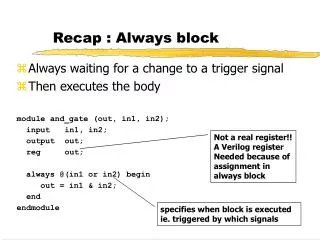
Recap : Always block • Always waiting for a change to a trigger signal • Then executes the body module and_gate (out, in1, in2); input in1, in2; output out; reg out; always @(in1 or in2) begin out = in1 & in2; end endmodule Not a real register!! A Verilog register Needed because of assignment in always block specifies when block is executed ie. triggered by which signals
Always block • A procedure that describes the function of a circuit • Can contain many statements including if, case • Statements in the always block are executed sequentially (except a case we will cover soon…) • The entire block is executed at once • The final result describes the function of the circuit for current set of inputs • intermediate assignments don’t matter, only the final result • begin/end used to group statements
“Complete” Assignments • If an always block executes, and a variable is not assigned • variable keeps its old value • NOT combinational logic latch is inserted • This is (most of the times) not what you want • Any variable assigned in an always block should be assigned for any execution of the block
Incomplete Triggers • Leaving out an input trigger usually results in a sequential circuit - again something we don’t usually want.. • Example: module and_gate (out, in1, in2); input in1, in2; output out; reg out; always @(in1) begin out = in1 & in2; end endmodule
Sequential Verilog • Sequential circuits are registers along with combinational logic • Register is synthesized when assignment is triggered by “posedge clk” module dreg (clk, d, q);input clk, d;output q;reg q; always@(posedge clk) q = d; endmodule
8-bit Register with Synchronous Reset module reg8 (reset, CLK, D, Q); input reset; input CLK; input [7:0] D; output [7:0] Q; reg [7:0] Q; always @(posedge CLK) if (reset) Q = 0; else Q = D; endmodule // reg8
N-bit Register with Asynch Reset module regN (reset, CLK, D, Q); input reset; input CLK; parameter N = 8; // Allow N to be changed input [N-1:0] D; output [N-1:0] Q; reg [N-1:0] Q; always @(posedge CLK or posedge reset) if (reset) Q = 0; else if (CLK == 1) Q = D; endmodule // regN
Blocking & Nonblocking Assignments • Blocking assignments (Q = A) • variable is assigned immediately before continuing to next statement • new variable value is used by subsequent statements • Non-blocking (delayed) assignments (Q <= A) • variable is assigned only after all statements already scheduled are executed • value to be assigned is computed here but saved for later • usual use: register assignment • registers simultaneously take their new values after the clock tick
Example always @(posedge CLK) begin temp = B; B = A; A = temp; end Swap : C style.. always @(posedge CLK) begin A <= B; B <= A; end But in hardware we can do things in parallel..
Example • All delayed assignments scheduled at the same time (even across always blocks) happen together • Another way to Swap : always @(posedge CLK) begin A <= B; end always @(posedge CLK) begin A <= B; end
What does this do? always @(posedge clk) begin {D, C, B} = {C, B, A}; end always @(posedge clk) begin B = A; C = B; D = C; end always @(posedge clk) begin B <= A; C <= B; D <= C; end
Counter Example // 8-bit counter with clear and count enable controls module count8 (CLK, clr, cntEn, Dout); input CLK; input clr; // clear counter input cntEn; // enable count output [7:0] Dout; // counter value reg [7:0] Dout; always @(posedge CLK) if (clr) Dout <= 0; else if (cntEn) Dout <= Dout + 1; endmodule
Mealy vs Moore machines • Mealy Machines - output depends on state as well as inputs. • Needs two always blocks - one for the state change (on posedge-clock) and one for the outputs. • Moore Machine - output depends only on state • Can do in one always block, but gets very confusing sometimes. • Best to always separate the “things happening on clock edge” and “things not happening on clk” into two always blocks.
0/0 zero[0] 1/0 0/0 one1[0] 1/1 Example: Mealy Machine module reduce (clk, reset, in, out); input clk, reset, in; output out; reg out; reg state; // state register reg next_state; parameter zero = 0, one = 1; //state assignment // the stuff that happens on “clock edge” always @(posedge clk) if (reset) state = zero; else state = next_state; // the “non clock” stuff always @(in or state) case (state) zero: begin // last input was a zero out = 0; if (in) next_state = one; else next_state = zero; end one: // we've seen one 1 if (in) begin next_state = one; out = 1; end else begin next_state = zero; out = 0; end endcaseendmodule
zero[0] 0 1 0 one1[0] 0 1 1 two1s [1] Moore Machine example • Change the first 1 to 0 in each string of 1’s • Example Moore machine implementation
Verilog code for Moore.. module reduce (clk, reset, in, out); input clk, reset, in; output out; reg out; reg [1:0] state; // state register reg [1:0] next_state; // State assignment parameter zero = 0, one1 = 1, two1s = 2; // Implement the state register always @(posedge clk) if (reset) state = zero; else state = next_state;
Verilog code for Moore.. // now for the part that “does not depend on the clock” always @(in or state) case (state) zero: begin // last input was a zero out = 0; if (in) next_state = one1; else next_state = zero; end one1: begin // we've seen one 1 out = 0; if (in) next_state = two1s; else next_state = zero; end two1s: begin // we've seen at least 2 ones out = 1; if (in) next_state = two1s; else next_state = zero; end default: begin // in case we reach a bad state next_state = zero; out = 0; endcaseendmodule