Download
1 / 9
90 likes | 159 Views
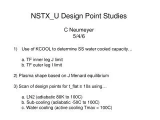
NSTX_U Design Point Studies C Neumeyer 5/4/6. 1) Updated Scan of design points for t_flat ≥ 10s using… a. LN2 (adiabatic 80K to 100C) b. Sub-cooling (adiabatic -50C to 100C) c. Water cooling (active cooling Tmax = 100C) Corrected error in solenoid flux requirement!!

E N D
NSTX_U Design Point Studies C Neumeyer 5/4/6 1) Updated Scan of design points for t_flat ≥ 10s using… a. LN2 (adiabatic 80K to 100C) b. Sub-cooling (adiabatic -50C to 100C) c. Water cooling (active cooling Tmax = 100C) Corrected error in solenoid flux requirement!! 2) Comments on implications of steady state operation
Constraints on Scans • Bt flat top for entire Ip≠0 duration • Ip_dot ramp-up = 5MA/s • Ip_dot ramp-down = 10MA/s • P_aux <= 10MW • Ti=Te, HH98<=1.2 • fGW>=0.1 • Solenoid provides 100% of ramp-up flux based on Hirschman-Neilson • w/Li=0.6 and CE=0.15 • T_max OH & TF conductor = 100C • _max OH & TF conductor = 138MPA (20ksi) • |I_oh| ≤ 24kA, V_oh=+/-8kV (2 anti-parallel strings of 8 PSS) • 36 turn TF coil • V_tf=+/-2kV (2 series x 10 parallel PSS) • Solutions optimized for maximum Ip
Cases Notes: Optimizer aims to maximize Ip in each case Some cases limited by non-inductive CD plus bootstrap limit at P_aux=10MW, others limited by TF and OH magnet limits
PPPL Infrastructure Constraints for Long Pulse And Steady State Operation (e.g. H2O cooled TF at 1T uses ~110MW just for TF) Aside from the magnets, we have to think about….. Power supplies (24kA-6s/300s, 3.25kA steady state) > Bt=1T @ 125kA per turn would use full TFTR TF power supply wing, leaving PF wing for OH and PF supplies > Bt above 1T would be doable for pulse lengths TBD or with purchase of additional power supplies $$$$ Site power > 138kV grid can supply ~ 200MW steady state (see next slide) > existing C-site substation transformers rated 2 @ 30/40/50MVA good for ~ 200MVA total pulsed but ~ 100MVA continuous > cabling C-site to D-site rated ~ 24MW > high steady state power at D-site would require 138kV extension and new substation at D-site (ala TPX proposal) Cooling water > existing cooling water system and towers probably designed to handle TFTR average power level ~ 24MW, would need significant upgrade to handle 100+ MW
Summary Comments Need to look at PPPL infrastructure capability to handle steady state power - could begin with long pulses and then upgrade facility to steady state Need to look at outer PF coils long pulse and steady state limits Need to look at TF outer legs structural issues at high field