Download
1 / 16
160 likes | 246 Views
NSTX_U Design Point Study Active H2O Cooling Pulse Length 60 sec. C Neumeyer 5/19/6. Physics Assumptions. Engineering Assumptions. TF Inner Leg Cooling. 200kA/turn 5 kA/cm^2 5.75m 10m/s fW=0.15. TF Outer Leg Cooling. 2” x 6” 3kA/cm^2 6.9m 10m/s fW=0.075. PF Cooling. R=2m

E N D
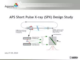
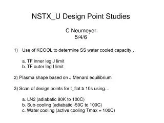
NSTX_U Design Point Study Active H2O Cooling Pulse Length 60 sec C Neumeyer 5/19/6
TF Inner Leg Cooling 200kA/turn 5 kA/cm^2 5.75m 10m/s fW=0.15
TF Outer Leg Cooling 2” x 6” 3kA/cm^2 6.9m 10m/s fW=0.075
PF Cooling R=2m I=15kA J=2.5kA/cm^2 Turn H and W are 1.25 times existing PF coils 10 turns/cooling path 10m/s
Divertor Cooling 4” dia pipes are adequate for divertor supply/return manifolds (assume full power capacity on top and bottom)
Fit inside VV 4” OD pipes 60mm W brush divertor
Facility Cooling TFTR ratings (may not be available anymore TBD)… Water tank = 33000 gallons (adequate) Cooling power = 20MW (adequate) Component cooling = 3300 GPM (~ 1/4 of requirement)
Power Supplies Use PS at 15kA per PSS (continuous rating of SCRs) Rep rate limited to ~ 1200s min due to 3.25kA rms rating Xfmrs OK (8 hrs) 5 parallel 750MCM per PSS ~ 50 parallel 1000MCM cables req’d for 200kA-60s/1200s
Approach Maximize Ip allowing solver to adjust of Jcu in inner and outer legs of TF subject to outer legs <= 2*CSA of existing
Conclusions How about…. A = 1.75 Ip = 3.0MA Bt = 1.5T oh = 1.5V-s P_aux = 30MW