Download
1 / 24
250 likes | 380 Views
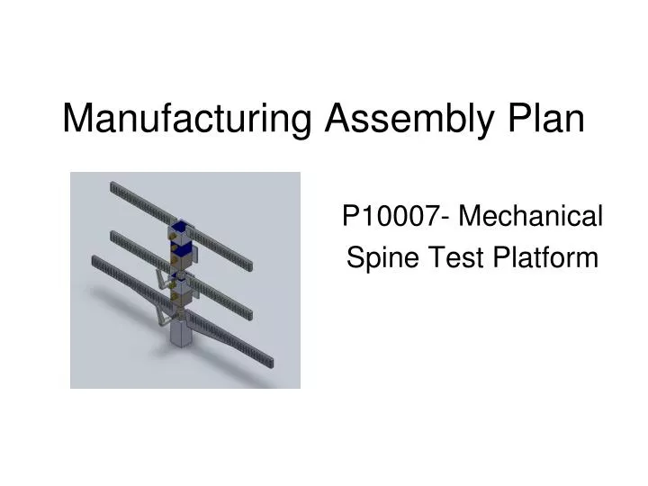
Manufacturing Assembly Plan. P10007- Mechanical Spine Test Platform. Base. Vertical adjustment:

E N D
Manufacturing Assembly Plan P10007- Mechanical Spine Test Platform
Base • Vertical adjustment: These are machined from 1" SQR x .125" and 1.25" SQR x .125" Tube Extruded Aluminum Bare Square Tube 6063 T52. Both rectangular tubes are cut to length using a band saw. Then the remaining material is milled out of the outer tube using an end mill. The holes are also drilled out of the outer tube using an end mill. To ensure a proper fit the touching surfaces may need to be filed down.
Base • Base plug The base plug is machined from 1" SQR 6061 Bar Extruded Aluminum Bare Square 6061 T6. First the base plug is cut to length using the band saw. Then an end mill is used to drill out the holes. • Wooden base The wooden base is made from a 3/4" AC Cabinet Grade Plywood. Pieces are cut to length and then glued. After our initial construction the wood seemed to deform slightly so a quick run over the bottom surface with an end mill ensures a flat bottom.
Base • Mounting Pad The mounting pad is machined from 1" SQR 6061 Bar Extruded Aluminum Bare Square 6061 T6. First the mounting pad is cut to length using the band saw. Then an end mill is used to fillet the edges and then drill the hole in the center.
Ball Joint • Upper Left / Right Joint These are machined from 1" SQR 6061 Bar Extruded Aluminum Bare Square 6061 T6. First the ball joint is cut to length using a band saw. Then an end mill is used to mill out the remaining material as well as drill the holes. It is important to use the same bit to mill both holes containing the aluminum ball in the upper and lower ball joint for consistency.
Ball Joint • Lower Left / Right Joint These are machined from 1" SQR 6061 Bar Extruded Aluminum Bare Square 6061 T6. First the ball joint is cut to length using a band saw. Then an end mill is used to mill out the remaining material as well as drill the holes. It is important to use the same bit to mill both holes containing the aluminum ball in the upper and lower ball joint for consistency. The pelvic ball joint is actually the top part of the telescope section.
Ball Joint • Ball Joint Stud • These are machined from 0.5" DIA 6061 T6 Extruded Aluminum Bare Round 6061 T6. • . First the stud is cut to length using a band saw. Then a lathe is used to reduce the diameters to their set lengths and thread one side. An end mill is then used to drill the hole. When threading it is crucial to be careful as the part is small. It is necessary to cut slightly into the base of the end that is threaded in order to ensure it can be threaded all the way.
Member • One Inch Segment These are machined from 1" SQR 6061 Bar Extruded Aluminum Bare Square 6061 T6. First the vertical segment is cut to length using a band saw. Then an end mill is used to mill out the remaining material as well as drill the holes. Looking back, it may have been better to have had these parts made using a CNC machine in order to have tighter tolerances. There were 8 made in all and some fit better than others so they were separated into two groups based on fit. Then to make them fit even better, each group was put into an end mill together and 5/1000 of an inch were taken off all sides to make them uniform.
Member/Ball Joint connection • Joint Receptacle This is machined from 1" SQR 6061 Bar Extruded Aluminum Bare Square 6061 T6. First the joint receptacle is cut to length using a band saw. Then an end mill is used to mill out the remaining material as well as drill the holes.
Horizontal Adjustment • Collar This is machined from 1.25" SQR x .125" 6063 T52 Tube Extruded Aluminum Bare Square Tube 6063 T52. First the collar is cut to length using a band saw. Then an end mill is used to mill out the remaining material as well as drill the hole. The inside of the collar may need to be filed down to allow smooth sliding over the members.
Horizontal Adjustment • Left and Right Horizontal The horizontal bars are made from .75" x .25" 6061 T6 Extruded Aluminum Bare Rectangle 6061 T6. First the horizontal bars are cut to length using a band saw. Then they are cut to shape and the hash marks indicating measurement are made in a CNC machine.
Pelvis • Left and Right Pelvis The left and right pelvises are machined from 1.25" x .125" 6061 T6 Extruded Aluminum Bare Rectangle 6061 T6 , 12". First the pelvises are cut to length using a bandsaw. Then an end mill is used to mill out the remaining material as well as drill out the hole. The hash marks indicating measurement are made in a CNC machine.
Sensor Mounting • Mounting Arm This is machined from 0.5" DIA 6061 T6 Extruded Aluminum Bare Round 6061 T6. First the mounting arm is cut to length using a band saw. Then an end mill is used to mill out the remaining material. • Sensor mount This is machined from 1.25" x .125" 6061 T6 Extruded Aluminum Bare Rectangle 6061 T6. First the sensor mount is cut to length using a band saw. Then an end mill is used to mill out the remaining material as well as drill out the holes.
First set the wooden base down with the uniformly flat side on top. Then Place the base plug in the square notch that was milled out of the top surface of the base. Place the bolt through the bottom of the base and screw it into the base plug until tight.
The next step is to weld the mounting pad to the side of the bottom of the stand (female part), to enable a more secure grip for the knob. Once this is done place the bottom part of the stand over the base plug and bolt it in securely. Next, place the top part of the stand into the bottom part and adjust to the desired height before tightening the knob.
After this the ball joint needs to be constructed. Screw the ball joint stud into the aluminum ball until flush. Next, secure the ball clamp of the lower ball joint to the pelvic ball joint (top part of the stand) with the aluminum ball in between, using two set screws to hold it in place. Screw in bolt until both sides fit tightly together. Then epoxy the ball joint stud into the joint receptacle.
The next step is to construct the collar. Weld the horizontal bars to the side surfaces of the collar.
Then construct the mount for the 3DM sensors. Weld the mounting arm to the sensor mount and then weld this to the back surface of the lower joint receptacle with the face of the sensor mount laying parallel to the ground.
The next step is to then weld the left and right pelvises onto the sides of the upper part of the stand. To adjust the height of the member (lower lumbar) add or remove the one inch vertical segments on top of each other and secure them in place with thumb screws.
After the sensor mount is successfully attached, place the collar over the joint receptacle. As the height is adjusted slide the collar up to the top vertical segment and secure it tightly using the same thumb screw as the top segment.
The next step is to then weld the left and right pelvises onto the sides of the upper part of the stand. To adjust the height of the member (lower lumbar) add or remove the one inch vertical segments on top of each other and secure them in place with thumb screws.
The next steps are the repeated from the construction of the lower lumber. Construct the upper ball joint using two set screws with the aluminum ball in between the left and right halves. Screw the ball joint stud into the aluminum ball until flush. Then place the ball joint inside the top vertical segment from the lower lumbar and tighten with a screw. Epoxy the ball joint stud into the joint receptacle. Then weld the horizontal bars to the side surfaces of the upper collar. Construct the mount for the 3DM sensor by welding the mounting arm to the sensor mount. Then weld this to the back surface of the joint receptacle with the face of the sensor mount laying parallel to the ground. Once complete place the collar over the joint receptacle. As in the lower lumber, adjust the height of the member (upper lumbar) by adding one inch vertical segments and securing them in place with thumb screws.
As the height is adjusted slide the collar up to the top vertical segment of the upper lumbar and secure it tightly using the same thumb screw as the top segment. Finally place 3DM sensors onto their corresponding sensor mounts and screw in until tight.