Download
1 / 36
360 likes | 473 Views
EUSO BALLOON INSTRUMENT Assembly, Integration and Tests Plan. Sylvie Dagoret-Campagne LAL. TABLE OF CONTENT. 1 Scope of the document 5 2 Documentation 5 2.1 Applicable documents 5 2.2 Reference documents 5 2.3 glossary 5 3 Instrument overview 6 3.1 Sybsystems configurations 8

E N D
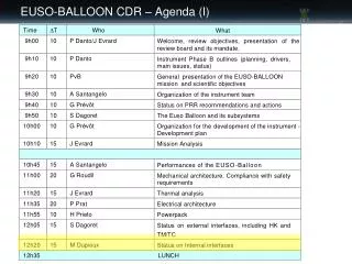
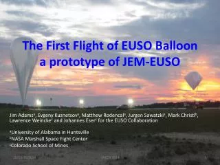
EUSO BALLOON INSTRUMENTAssembly, Integration and Tests Plan Sylvie Dagoret-Campagne LAL 9th EUSO-B Progress Meeting, Naples, November 9th 2012
TABLE OF CONTENT 1Scope of the document 5 2Documentation 5 2.1Applicable documents 5 2.2Reference documents 5 2.3glossary 5 3Instrument overview 6 3.1Sybsystems configurations 8 3.1.1EUSO Balloon instrument in C1 configuration 8 3.1.2EUSO Balloon instrument in C2 configuration 9 3.1.3EUSO Balloon instrument in FLIGHT configuration 9 4AIT organisation 9 4.1General overview of the AIT 9 4.2Constitution of the AIT teams 10 4.3Management 10 4.3.1Schedule and activities Management 10 4.3.2TraçabilitY 11 4.3.3Risk 11 5GROUND FACILITIES 11 5.1Electrical Segment Equipement 11 5.2Photometric Segment Equipement 11 5.3Mechanical Segment Equipement 11 5.4Optical Segment Equipement12 9th EUSO-B Progress Meeting, Naples, November 9th 2012
6. subsystem AIT activity 12 6.1PDM 12 6.1.1AIT activities overview 12 6.1.2PDM AIT detailed activities 16 6.1.3PDM delivery to the instrument 31 6.2DP AIT activities 31 6.2.1AIT activities overview 31 6.2.2DP AIT detailed activities 31 6.2.3DP delivery to the instrument 35 6.3Lenses AIT activities 35 6.3.1AIT activities overview 35 6.3.2Lenses AIT detailed activities 35 6.3.3Lenses delivery to the instrument 35 6.4PWP AIT Activity 35 9th EUSO-B Progress Meeting, Naples, November 9th 2012
7EUSO Balloon Instrument AIT activities 36 7.1Activities overview 36 7.2AIT of the Instrument phase 1 37 7.2.1Preparation of the mechanical integration 37 7.2.2Assembly of the electrical section 37 7.2.3Good health tests 38 7.2.4Assembly of the Optical Section 38 7.2.5Optical alignment 39 7.3AIT of the Instrument phase 2 39 7.3.1Functional tests of the TM with NOSYCA 39 7.3.2Autonomous gondola tests 40 7.3.3Campaign simulation tests 40 7.4AIT of the Instrument phase 3 40 7.4.1disassembly of the instrument 40 7.4.2Instrument packaging for transportation 41 7.5AIT of the Instrument phase 4 41 7.5.1Reception control and preparation 41 7.5.2Assembly of the whole instrument 41 7.5.3Optical alignment of the instrument 41 7.5.4Instrument good health tests 41 7.5.5Gondola finalization 42 7.5.6Instrument recovery 42 7.5.7Instrument integrity control 42 7.5.8Instrument packaging for transportation 42 9th EUSO-B Progress Meeting, Naples, November 9th 2012
INSTRUMENT OVERVIEW 9th EUSO-B Progress Meeting, Naples, November 9th 2012
DP PDM EC-Front GPSR IR-CAM EC-DYNODE CLKB LVPS-DP1 EXT MAPMT EC-HV CCB EC-ANODE SIREN SPACEWIRE /PCI CNES Telemetry CPU EC-ASIC LVPS-DP2 DST Batteries PDM-B Bat Controller LVPS-PDM HVPS2 PWP HK HVPS1 LVPS-HK Sensors Motors EC-Back TLS 9th EUSO-B Progress Meeting, Naples, November 9th 2012
PDM AIT 9th EUSO-B Progress Meeting, Naples, November 9th 2012
Component Manufacturing Integration Tests & Validation Component Pre-assembly Pre- Integration Component test Assembly PAECM1 EC-Unit PAECM2 IEC1 AP1 IEC2 AP3 CAPHEC1 HVPS THV1 THV2 IEC3 TECA1 AP2 EC-ASIC TECA2 IEL1 TrigPDM IEL2 PDM-B TPD1.. N 9th EUSO-B Progress Meeting, Naples, November 9th 2012
Pre-Integration IEC3(@APC) NIM/CAMAC Light Source & Opt. Bench Power 28 V HV Box (1) EC-Unit 1 Power 3.3 V & 1.5 V Test-EC-Unit (2- ?) FAST-DAQ Or LAbView EC-ASICs 1 Special EC Frame (1) • Slow control parameters can be downloaded and read back, • Trigger curves obtained by DAC threshold slopes (S-Curves) measured on each of the 64 channel of the photon counting, • No particular check will be done on KI channels at this stage. 9th EUSO-B Progress Meeting, Naples, November 9th 2012
Assembly HV Box (1) EC-Unit (9) AP1 AP2 EC-ASICs (6) PDM Frame (1) EC-Unit (9) 256 HV cables EC-ASICs (6) 36 EC-Anode Flex PDM Frame (1) 9th EUSO-B Progress Meeting, Naples, November 9th 2012
Integration AP1,AP2,AP3, CAPHEC1(APC) NIM/CAMAC Light Source & Opt. Bench Power 28 V HV Box (1) EC-Unit (9) Power 3.3 V & 1.5 V Test-EC-Unit (2- ?) FAST-DAQ Or LAbView EC-ASICs (6) PDM Frame (1) • Assembly (AP1,AP2,AP3) : mount all Electronicsat the rear of the PDM • EC-ASIC • HV • Integrationput the cables in the connectors: • Connect the EC-Units to the EC-ASIC through the FS frame though the EC-Anode flexcables, • Test and validation , CAPHEC1 at APC • Photon detectionefficiency for eachchannel, • Gain of each MAPMT, • Electronic gain matching • S-Curves for each pixel, • KI-S-curve, • Voltage for each EC, 9th EUSO-B Progress Meeting, Naples, November 9th 2012
Test and Validation CAPHEC1 (Calibration@APC) HVPS K and dynodes HV 900 V Integrand sphere EC-ASIC TEST-ECASIC EC-Units LED collimators • Data analysis for each of • the 64 channels • Quantum efficiency • Gain Photocathode Uniform illumination In single photoelectron mode Pulser 9th EUSO-B Progress Meeting, Naples, November 9th 2012
Trigger Validation TrigPDM HVPS K and dynodes HV 900 V FS EC-Units EC-ASIC PDMB Absorber To work in UV and low light mode 9th EUSO-B Progress Meeting, Naples, November 9th 2012
ElectronicIntegration IEL1 (Resp LAL) PDM-B Analysistools (1) (6) Pulse Generator PDM-B EC-ASIC 40 MHz clock 5 V PDM-B 5 V EC-ASICs 9th EUSO-B Progress Meeting, Naples, November 9th 2012
ElectronicIntegration IEL2 (Resp LAL) CPU software PDM-B EC-ASIC Pulse Generator LAL (1) (1) (6) DP clock 4 x 28 V 9th EUSO-B Progress Meeting, Naples, November 9th 2012
Final PDM Integration AP4 (APC) NIM/CAMAC Light Source & Opt. Bench Power 28 V HV Box (1) EC-Unit (9) Power 5 V EC-ASICs (6) PDM-B (1) PDM Frame (1) • Assembly (AP4) : put all calblesat PDM-B • EC-ASIC • HV • Integrationput the cables in the connectors: • Connect the EC-Units to the EC-ASIC through the FS frame though the EC-Anode flexcables, • Test and validation • Test EC-ASICs R&W by PDM-B to retrieve LAL integration tests 9th EUSO-B Progress Meeting, Naples, November 9th 2012
LVPS DP1 LVPS HK HK CPU LVPS DP2 GPSR LVPS PDM CCB CLKB INTEGRATION OF DP 9th EUSO-B Progress Meeting, Naples, November 9th 2012
Summary of DP Integration (@Naples) • 3 monthes (TBC) • Mechanical and electrical compatibility • Hardware tests • Software tests UNAM+ INFN(Na-Ba-Roma2) UNAM+ INFN(Na-Ba-Roma2) IAAT+ Naples+ Bari IAAT+ (Na-Ba-Roma2) IAAT+ (Na-Ba-Roma2) ID2: +GPS+CLK+SPI ID1: LVPS+ HK+CPU ID3: +CCB ID4: +CCB+SPI ID5: SpaceWire 9th EUSO-B Progress Meeting, Naples, November 9th 2012
DP Integration Phase 1 (ID1) DP-Box • Integration ID1 : participants UNAM, Naples/INFN, Bari/INFN and Roma2/INFN The first step of the integration will regard the LVPS modules, the HK and the CPU. During this phase, after the verification of all the mechanical and electrical compatibilities, the communication between CPU and HK system on the RS422 port will be faced and tuned. (HK configuration, switch-on/off sequence etcetc) LVPS HK CPU RS422 DP-Box 9th EUSO-B Progress Meeting, Naples, November 9th 2012
DP Integration Phase 2 (ID2) DP-Box • Integration ID2 : participants UNAM and INFN (NA-BA-Roma2) the introduction in the system of the CLK board and GPS board in order to test the relative LVPS and to verify the SPI interfaces HK-CLKb and HK-GPSb. The interface CLKb-GPSb with the two boards powered by the LVPS will be tested too. LVPS CPU HK SPI CLK GPS DP-Box 9th EUSO-B Progress Meeting, Naples, November 9th 2012
DP Integration Phase 3 (ID3) DP-Box Integration ID3 : participants IAAT and INFN (Na-Ba-Roma2) the introduction in the system of the CCB. Also in this case we have to test mechanical and electrical compatibilities, the interface with CLKb in order to provide a clock to the board and all the ancillary functionality. CPU LVPS HK SPI PDM-B Emulator CLK CCB GPS DP-Box 9th EUSO-B Progress Meeting, Naples, November 9th 2012
DP Integration Phase 4 (ID4) DP-Box Integration ID4 : participants IAAT, UNAM and INFN(NA-BA-Roma2) we have to test the SPI interface HK-CCB LVPS HK CPU SPI PDM-B Emulator CLK CCB GPS DP-Box 9th EUSO-B Progress Meeting, Naples, November 9th 2012
DP Integration Phase 5 (ID5) DP-Box Integration ID5 : participants IAAT and INFN (NA-BA-Roma2) The fivethstep will be the test of the the SpaceWire interface and the full simulation of the different operational mode of the system. LVPS HK CPU SpaceWire SPI PDM-B Emulator CLK CCB GPS DP-Box 9th EUSO-B Progress Meeting, Naples, November 9th 2012
Integration of PWP 9th EUSO-B Progress Meeting, Naples, November 9th 2012
Integration of PWP1 Power Pack box: Riken PWP AP1: PWP Assembly TP1: Test of PWP IP1: Integration of PWP Batteries cells : CNES Test of the PWP (external power as well as batteries ) IRAP Integrationwith the electronics IRAP Assembly of the cells Inside the PWP box IRAP 9th EUSO-B Progress Meeting, Naples, November 9th 2012
FINAL INTEGRATION 9th EUSO-B Progress Meeting, Naples, November 9th 2012
FINAL PDM+DP Integrationbefore IRAP Power 28 V/PWP NIM/CAMAC Light Source & Opt. Bench HV Box (1) EC-Unit (9) DP LVPS3 DP LVPS2 DP LVPS1 HK CPU EC-ASICs (6) PDM-B (1) PDM Frame (1) PDM LVPS CCB GPSR CLKB • Assemblyconnect PDM-B to DP • CCB, HK • Integrationput the cables in the connectors: • Connect the EC-Units to the EC-ASIC through the FS frame though the EC-Anode flexcables, • Test and validationDatafrom CPU to computer / fromstorage, Monitoring, 9th EUSO-B Progress Meeting, Naples, November 9th 2012
Optics 9th EUSO-B Progress Meeting, Naples, November 9th 2012
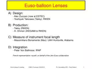
Lenses 9th EUSO-B Progress Meeting, Naples, November 9th 2012
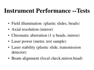
Validation and Acceptance tests for the lenses RIKEN : estimation of the Focal length of eachlens in visible and UV.s UAH : precisionmeasurement Of the focal length of eachlens In UV 9th EUSO-B Progress Meeting, Naples, November 9th 2012
BACKUP 9th EUSO-B Progress Meeting, Naples, November 9th 2012
DP PDM EC-Front GPSR IR-CAM EC-DYNODE CLKB LVPS-DP1 EXT MAPMT EC-HV CCB EC-ANODE SIREN SPACEWIRE /PCI CNES Telemetry CPU EC-ASIC LVPS-DP2 DST Batteries PDM-B Bat Controller LVPS-PDM HVPS2 PWP HK HVPS1 LVPS-HK Sensors Motors EC-Back TLS 9th EUSO-B Progress Meeting, Naples, November 9th 2012
DP PDM EC-Front GPSR IR-CAM EC-DYNODE CLKB LVPS-DP1 EXT MAPMT EC-HV CCB EC-ANODE SIREN SPACEWIRE /PCI CNES Telemetry CPU EC-ASIC LVPS-DP2 DST Batteries PDM-B Bat Controller LVPS-PDM HVPS2 PWP HK HVPS1 LVPS-HK Sensors Motors EC-Back TLS 9th EUSO-B Progress Meeting, Naples, November 9th 2012
EC-Front GPSR IR-CAM EC-DYNODE CLKB LVPS-DP1 EXT MAPMT EC-HV CCB EC-ANODE SIREN SPACEWIRE /PCI CNES Telemetry CPU EC-ASIC LVPS-DP2 DST Batteries PDM-B Bat Controller LVPS-PDM HVPS2 PWP HK HVPS1 LVPS-HK Sensors Motors EC-Back TLS 9th EUSO-B Progress Meeting, Naples, November 9th 2012
Pre-Assembly of EC-Front Units Voltage divider HV 900 V Integrand sphere K and dynodes QADC MAPMT 64 anodes Photocathode Uniform illumination In single photoelectron mode LED Gate • Data analysis for each of • the 64 channels • Quantum efficiency • Gain Pulser 9th EUSO-B Progress Meeting, Naples, November 9th 2012