Download

1 / 35
370 likes | 522 Views
Memory Systems. Main Memory Invariably comprises solid state semiconductor devices Interfaces directly with the three bus architecture of the computer system. Operates at speeds consistent with the speed of the processor . Characterised by relatively high cost per bit of storage.

E N D
Main Memory • Invariably comprises solid state semiconductor devices • Interfaces directly with the three bus architecture of the computer system. • Operates at speeds consistent with the speed of the processor. • Characterised by relatively high cost per bit of storage. • Many types of semiconductor memory loses stored data when the power is removed from the device. (volatile) • Secondary Memory • Invariably electromechanical devices - CDs, discs, tapes etc • Interfaces to the system busses via I/O devices such as disc controllers. • For the processor to use data stored in secondary memory it must first be transferred to main memory. • Characterised by very low cost per bit of storage and is non-volatile. Memory Classes
Random Access Memory (RAM) • The processor can save data in RAM - memory write operation • The processor can retrieve data from RAM - memory read operation • In most cases RAM is volatile - i.e. stored data lost when power removed. • There are two types of RAM : • Static RAM - Provided electrical power is maintained the data, once stored, remains stored indefinitely unless overwritten. • Dynamic RAM - Data stored in dynamic RAM is lost unless it is read on a regular basis ( typically once per ms ) • Read Only Memory (ROM) • Non-volatile memory which can only be read by the processor. • Special programming facilities are required to store data in ROM. • ROM is often used for program storage in systems without secondary memory. Types of Main Memory
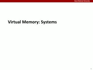
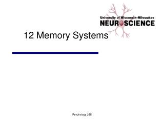
8k x 8 RAM Chip RAM Architecture
Total number of memory cells per chip • number of locations x number of bits per location • (8192 x 8 = 65536 in the example) • Memory cells are organised as a square matrix • ( 256 rows x 256 columns in the example ) • A row of the matrix is selected by one output of the row decoder. The row decoder accepts n address bits and decodes them into 2n outputs. • ( n = 8 selects 1 of 256 rows in the example ) • A row of the matrix can be considered to comprise a number of locations • ( a row comprises 32 locations in the example ) Memory Architecture
The column decoder selects a location in a row of the matrix. • A column of the matrix is selected by one output of the column decoder. The column decoder accepts m address bits and decodes them into 2m outputs. • ( m = 5 selects 1 of 32 columns in the example ) • The total number of address bits required to specify a location within the memory device is m + n • ( m + n = 13 in the example Note: 213 = 8192 ) Memory Architecture
Once the memory device receives address information ( 13 binary digits on inputs A0 - A13 in the example )the decoding logic selects the addressed location. • The addressed location is interfaced to the external data bus via back-to-back tri-state buffers. • The memory device’s data bus input buffers are enabled when the device receives an asserted WR/ signal and data on the external bus gets written to the addressed memory location. • The memory device’s data bus output buffers are enabled when the device receives an asserted RD/ signal and data at the addressed memory location is placed on the external bus for an external device to read. Memory Operation
The chip enable inputs, CE1*and CE2 permit memory systems to comprise more than a single memory device. • To provide the required memory system for a computer application may require tens or even hundreds of memory devices. Truth Table for Memory Device Control Logic
When the processor wishes to read or write to memory, it specifies the memory location to be involved in the data transfer by its address. • The addressed memory location and only the addressed memory location, should respond if the computer is to perform correctly. • It is incumbent on the memory devices themselves and memory decoding logic external to the processor, to ensure this happens. Memory System Design
A certain 8085A based microcomputer system has the following memory specifications : • 2K ROM starting at address 0000 H to be implemented with a 1 off 2716 ROM ( the 2716 is organised 2K x 8 ) • 4K ROM starting at address F000 H to be implemented with a 1 off 2732 ROM ( the 2732 is organised 4K x 8 ) • 16K RAM starting at address 0800 H to be implemented with 8 off HM6116 RAM ( the 6116 is organised 2K x 8 ) • Draw the memory map • Develop the decoding logic • Draw a schematic diagram of the complete system Example of Memory System Design
The memory devices Example of Memory System Design
The memory map is a pictorial representation of where the memory blocks are located in the total address space of the processor Example of Memory System Design
The coloured addresses in the diagram are decoded internally by the devices. • The addresses not coloured have to be externally decoded and used to drive the chip selects of the respective devices. Decoding Logic Example of Memory System Design
Exhaustive Decoding • When all the address lines of the processor (either by the internal device decoders or external memory decoders) are used to specify the address of a memory location, exhaustive decoding is said to be used. • The preceding example uses exhaustive decoding for all memory devices. • Partial Decoding • If one or more of the processors address lines are not used by either the external memory decoders or internal device decoders to specify an address then partial decoding is said to be used. Memory Decoding Systems
It is only possible to interface the full compliment of memory to a microprocessor if exhaustive decoding is used for all the memory devices. • If one address line is not used to specify a memory location then the location will respond to 2 different processor addresses. • If two address line are not used to specify a memory location then the location will respond to 4 different processor addresses. • If three address line are not used to specify a memory location then the location will respond to 8 different processor addresses. Etc, etc Memory Decoding Systems
Memory device receives valid address from processor. Internal decoding logic selects addressed location. • Memory CS/ control line asserted. Usually supplied from external decoding logic fed by higher order processor address lines. • Memory OE/ control line asserted. Usually driven by processor RD/ control line. • Memory device enables its output data bus buffers and data at the addressed location is placed on the data bus for the processor to read. • Processor de-asserts its CS/ and/or RD/ control lines causing the memory device to tri-state its data bus drivers. Memory Read Cycle - Sequence
For a device to read the contents of a memory location without error certain timing constraints must be adhered to. • The time it takes for an integrated circuit to carry out a certain function varies from device to device. • Manufacturers specify timing constraints for integrated circuits as either maximum or minimum values. • Maximum or minimum values are specified (sometimes both) so that systems may be designed which will operate without error. Memory Read Cycle - Timing Constraints
tRC read cycle min • This represents the minimum time to carry out a successful read operation (assuming all other constraints are met) • tACS chip select access max • This represents the maximum time it takes the memory device from CS/ being asserted to valid data appearing on the data bus.(assuming all other constraints are met) • tAA address access max • This represents the maximum time it takes the memory device from it receiving valid address to valid data appearing on the data bus.(assuming all other constraints are met) Memory Read Cycle - Timing Constraints
tRDHA read data hold after address min • This represents the minimum time the memory device will keep valid data on the data bus after a change of address. (assuming cs/ and oe/ remain asserted) • tRDHC read data hold after chip select min • This represents the minimum time the memory device will keep valid data on the data bus after being deselected. (assuming valid address and oe/ remain asserted) • tOE output enable access max • This represents the maximum time it takes the memory device to place valid data on the data bus after oe/ is asserted. (assuming other constraints are met) • tOHZ output enable to output Hi-z max • This represents the maximum time it takes the memory device to tri-state its output buffers after oe/ is de-asserted. Memory Read Cycle - Timing Constraints
The processor specifies the memory location at which the data is to be stored. Internal memory decoding logic selects the desired location. • External decoding logic asserts the cs/ input to the memory device. • The processor asserts the wr/ control input of the memory device. This enables its tri-state input buffers. • The processor places the data to be stored onto the data input lines of the memory device. • The processor de-asserts the wr/ control line. The rising edge of wr/ latches the data into the specified location and also tri-states the device’s input buffers. Memory Write Cycle - Sequence
tWC write cycle min • This represents the minimum time to carry out a successful write operation (assuming all other constraints are met) • tCW chip select to end of write min • This represents the minimum time that the chip select signal must remain asserted. (assuming all other constraints are met) • tAS address set-up time min • This represents the minimum time valid address must be present on the memory device’s address lines before wr/ is asserted. • tMWE write enable min • This represents the minimum time wr/ must be asserted. Memory Read Cycle - Timing Constraints
tAW address valid to end of write min • This represents the minimum time the address must remain valid before wr/ is de-asserted. (assuming all other constraints are met • tWDS write data set-up time min • This represents the minimum time data must be valid before the rising edge of wr/. • tWDHE write data hold-time min • This represents the minimum time data must remain valid after the rising edge of wr/. Memory Read Cycle - Timing Constraints
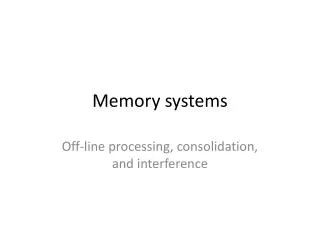
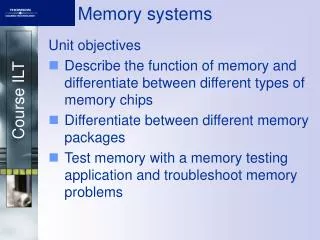
Design a memory system for a 8085A based microcomputer system with the following memory specifications : • ROM ( the 27C64 is organised 8K x 8 ) • RAM ( the 6264 is organised 8K x 8 ) • Draw the memory map • Develop the decoding logic • Draw a schematic diagram of the complete system Example
5FFFH 4000H 2 X 8K x 8 6264 RAM 3FFFH 2000H 1FFFH 1 X 8K x 8 27C64 EPROM 0000H
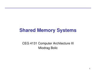
3-TO-8 LINE DECODER 74LS138
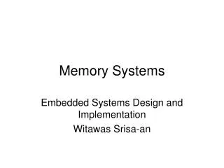
Analogue to Digital Converter ADC0804 and seven segment display connected to 8085 microprocessor through 8255 I/O port. Connections: DB0 – DB7 (Digital data) ---- Port A SC signal (/WR) ---- PC0 EOC signal (/INTR) ---- PC4 Analogue input (Vin) ---- Sensor */CS & /RD pull to ground Seven segment display (Common cathode) ---- Port B