Download
1 / 60
600 likes | 714 Views
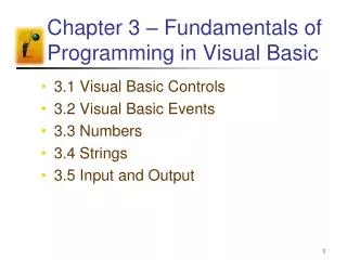
Chapter Five Part 2: Control. Control. Selecting the operations to perform (ALU, read/write, etc.) Controlling the flow of data (multiplexor inputs) Information comes from the 32 bits of the instruction

E N D
Control • Selecting the operations to perform (ALU, read/write, etc.) • Controlling the flow of data (multiplexor inputs) • Information comes from the 32 bits of the instruction • Example: add $8, $17, $18 Instruction Format: 000000 10001 10010 01000 00000 100000 op rs rt rd shamt funct • ALU's operation based on instruction type and function code
Overview of MIPS • three instruction formats op rs rt rd shamt funct R I J op rs rt 16 bit address op 26 bit address
Machine Language • R-Instruction Format:000000 10001 10010 01000 00000 100000 op rs rt rd shamt funct op: op code rs: the first register source operand rt: the second register source operand rd: the register destination operand; gets result shamt: shift amount (see chap 5) funct: function; selects the variant of the operation in the op field.
Branches and Jumps • Instructions: bne $t4,$t5,LabelNext instruction is at Label if $t4 ° $t5 beq $t4,$t5,LabelNext instruction is at Label if $t4 = $t5 j LabelNext instruction is at Label • Formats: op rs rt 16 bit address I J op 26 bit address
Control • Must describe ALU control hardware to compute 3-bit ALU control input • Later will describe main control unit (CU) • Common to use several levels of control. Reduces size of CU. May increase speed of CU.
Control • ALU performs differently depending on instruction class: • Load/store: use ALU to compute memory address (addition) • R-type: performs one of 5 actions depending on value of the 6-bit function field. • Branch: ALU subtracts
Control ALU control unit inputs: • function field of instruction • 2-bit control field called ALUop. Sent by the main control unit. • ALUop determined by instruction type 00 = lw, sw means ADD 01 = beq, means SUB 11 = arithmetic means use the function code • ALU control unit outputs: • 3-bit signal to the ALU
Control Design question: Why do we have a funct field in the R-type instruction? Why not just more op-codes? Already used up the available op-codes Since the R-type instruction doesn’t use 32 bits for the register fields, have extra space that we can use for the funct field
Control • ALU control input (3 bit control line to ALU) 000 AND 001 OR 010 add 110 subtract 111 set-on-less-than • Why is the code for subtract 110 and not 011?
Control Instruction from memory Main Control unit Bits 31-26 opcode ALU ALUOp 2 bits ALU Control unit 3 bits Bits 5-0 funct ALU control code
Control • Below: how to set ALU control inputs based on the 2-bit ALUOp control and the 6-bit function code.
ALU Control hardware implementation • Many ways to implement the mapping from 2-bit ALUOp field and 6-bit funct field to the 3 ALU operation control bits. • Only need a small number of the 64 possible values of the funct field • funct field only used when ALUOp bits equal 10. • So can design small logic that recognizes a subset of possible values and sets the ALU control bits.
ALU Control implementation • Technique: • Look for unique bits that will identify a particular output function. • Example: • Branch eq has ALUOp = 01. No other code has a 1 in the least significant bit. • Thus the 1 in the lsb uniquely identifies the branch and thus uniquely identifies ALU code 110. • The bit in the msb of ALUOp is a don’t care condition in this case. • See next slide
ALU Control implementation • Example 2: • A 1 in the msb of ALUOp uniquely identifies the arithmetic function. • Thus the lsb of ALUOp is a don’t care • Also, funct bits 5 and 4 are always 10, thus don’t help recognize the ALU control bits and can be ignored.
ALU Control implementation • Describe it using a truth table (can turn into gates). • Notes: • Inputs are the ALUOp and funct code field • Only show entries for which ALU control must have specific value, eg ALUOp does not use 11 so table contains 1X and X1 not 10 and 01 • When funct field used, the first two bits (F5, F4) are always 10, so they are don’t care terms
ALU Control implementation • Implementing the TT. Call the output bits Op2, Op1, Op0. • Truth table for Op2 = 1 (leftmost bit of Operation field in previous table) • Only show entries for which output is 1. • Truth table above shows input combinations for which the ALU control is 010, 001, 110, 111. • Combinations 011, 100, and 101 are not used. • Don’t care about funct code if the ALUOp field is not 10.
ALU Control implementation • Truth table for Op2 = 1 (leftmost bit of Operation field in previous table)
ALU Control implementation Truth table for Op1 = 1 (middle bit of Operation field in bottom table)
ALU Control implementation • Truth table for Op0 = 1 (rightmost bit of Operation field in bottom table)
Full Control Implementation • Have now designed the ALU control • Must design the full control logic
Control • 3 instruction formats: R-type 0 rs rt rd shamt funct 31-26 25-21 20-16 15-11 10-6 5-0 Load/Store 35 or 43 rs rt address 31-26 25-21 20-16 15-0 Branch 4 rs rt address 31-26 25-21 20-16 15-0
Control • Opcode is always in bits 31-26. Refer to this as Op[5-0] • Two registers to read are always rs and rt at positions 25-21 and 20-16. True for R-type, branch, store.(rt) • Base register for load and store is always in bit positions 25-21 (rs) • The 16-bit offset for branch equal, load, store always in bit positions 15-0 • Destination register is in one of two places: • Load: positions 20-16 • R-type: positions 15-11 (rd) • Need a mux to select this • Can now add labels, muxes, control lines to datapath. See next slide.
Control Added: instruction labels, extra mux (for Write register number input of the register file) to datapath, ALU control block, write signals for state elements, read signal for data memory, control signals for multiplexors.
Control • The control unit can set all but one of the control signals based on the opcode • PCSrc is set if instruction is branch on equal and Zero output of ALU is 1. • Control units and signals added to datapath on next slide • Table on next slide defines how the control signals should be set for each opcode.
Control Datapath with control lines and control units
Control: use of the datapath • R-type instructions. Four steps (all are done in one clock cycle) • Signals stabilize in circuit in roughly the order of these 4 step • Example: add $t1, $t2, $t3 • Step 1: Fetch and increment PC.
Control: use of the datapath • Step 2: Two registers are read ($t2 and $t3). • Main CU computes setting of control lines.
Control: use of the datapath • Step 3: ALU operates on data using the function code bits.
Control: use of the datapath • Step 4: Result from ALU written into register file (register $t1).
Control: use of the datapath • Execution of a load word: lw $t1, offset($t2) • Step 1: instruction fetched and PC incremented • Step 2: A register ($t2) value is read • Step 3: The ALU computse the sum of the register valuie and the sign-extended lower 16 bits of the offset • Step 4: the sum from ALU used as the address for data memory • Step 5: The data from memory written into the register file. Register destination given by bits 20-16 of the instruction ($t1)
Control: use of the datapath • The load word instruction ( lw $t1, offset($t2) )
Control: use of the datapath • Branch equal instruction beq $t1, $t2, offset • Step 1: instruction fetched, PC incremented • Step 2: two registers read ($t1, $t2) • Step 3: ALU subtracts. PC + 4 added to the sign-extended lower 16 bits of the instruction (offset) shifted left by two. Result is the branch target • Zero result used by CU to decide which adder result to store into the PC • Diagram next slide.
Control: use of the datapath • Branch equal instruction beq $t1, $t2, offset
Finalizing Control • Instruction formats and resulting control signals • Encoding of the instruction formats:
Finalizing Control • Implementing jumps • Similar to branch but computes target differently and is not conditional • Low-order 2 bits always 00 • Next lower 26 bits come from the 26-bit immediate field • Upper 4 bits of the address come from the PC of the jump instruction + 4 2 address 31-26 25-0
Finalizing Control • Implementing jumps • To implement, store into PC the concatenation of • Upper 4 bits of current PC + 4 (bits 31-28) • The 26-bit immediate field of the jump instruction • The bits 00 • Need additional multiplexor • Incremented PC • Branch target PC • Or the jump target PC • Need additional control signal called jump. Asserted when opcode is 2.
Exercise • Add an instruction that adds a register value with a memory value. • How must the datapath change to accommodate this instruction? • What new control signals are necessary?
Exercise: R + M -> R 0 1 Problem: what is the address size? Must sign extend
Our Simple Control Structure • All of the logic is combinational • We wait for everything to settle down, and the right thing to be done • ALU might not produce “right answer” right away • we use write signals along with clock to determine when to write • Cycle time determined by length of the longest path We are ignoring some details like setup and hold times
Single Cycle: why it is not used • Bottom line: it’s inefficient. • Every clock cycle must have same length for every instruction. • Clock cycle determined by the longest possible path in machine • In this instruction set: load instruction • Load uses 5 functional units in series: • Instruction memory • Register file • ALU • Data memory • Register file • Thus cycles per instruction (CPI) is 1.