Download
1 / 68
720 likes | 1.13k Views
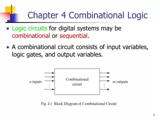
Chapter 4 Combinational Logic. Combinational Logic Circuit. Combinational circuit : logic circuit whose outputs at any time are determined directly and only from the present input combination.

E N D
Combinational Logic Circuit • Combinational circuit: logic circuit whose outputs at any time are determined directly and only from the present input combination. • A combinational circuit performs a specific information-processing operation fully specified logically by a set of Boolean functions. • Sequential circuit: one that employ memory elements in addition to (combinational) logic gates—their outputs are determined from the present input combination as well as the state of the memory cells.
Introduction • The state of the memory elements, in turn, is a function of the previous inputs (and the previous state). • Its behavior therefore is specified by a time sequence of inputs and internal states. • In many applications, the source and the destination are storage registers. • A combinational circuit also can be described by m Boolean functions, one for each output variable.
Block Diagram of a Combinational Circuit Combinational Circuit n inputs m outputs Fig. 4-1: Block Diagram of Combinational Circuit
Analysis Procedure ABC (A + B + C)(AB + AC + BC)’ + ABC A + B + C AB (AB + AC + BC)’ AB + AC + BC AC BC
Design Procedure 1. Define the problem. 2. Determine the number of input/output variables. 3. Assign letter symbols to input/output variables. 4. Derive the truth table and defines the required relationships between inputs & outputs via KM. 5. Obtain the simplified Boolean function for each output. 6. Draw the logic diagram.
Adder • The most basic arithmetic operation is the addition of 2 bits. A combinational circuit that performs this operation is called a half-adder. • A combinational circuit that performs the addition of 3 bits is called a full-adder, which can be implemented by 2 half-adders.
Implementation of FA S = z (x y) = z’(xy’ +xy’) + z (xy’ +x’y)’ = z’(xy’ +x’y) + z(xy + x’y’) = xy’z’ + x’yz’ + xyz + x’y’z The carry output is C = z(x’y + xy’) + xy = xy’z + x’yz + xy
Binary Subtractor • Subtraction = addition of minuend and 2’s-complemented subtrahend. • Also can implement subtraction directly—with half-subtractors and full-subtractors.
Code Conversion • The expressions obtained may be manipulated algebraically for the purpose of using common gates for 2 or more outputs. w = A + BC + BD = A + B(C + D) x = B’C + B’D + BC’D’ = B’(C + D) + B(C + D)’ y = CD + C’D’ = CD + (C + D)’ z = D’
Binary Adder • Iterative Logic Array (ILA)
Binary subtractor • Iterative Logic Array (ILA)
طراحي مدار جمعكنندة BCD مداري است كه دو عدد BCD را بعنوان ورودي پذيرفته و مجموع آنها را بصورت يك عدد BCD چهار بيت، همراه با يك بيت نقلي توليد ميكند. از آنجا كه هر عدد BCD از 0 تا 9 ميباشد ولي داراي چهار رقم است، شش حالت بلااستفاده وجود دارد كه بعنوان حالات بيتفاوت در نظر گرفته ميشوند. هر عدد BCD حداكثر ممكن است 9 باشد. با فرض اينكه هر دو برابر با 9 باشند و بيت نقلي از مرحلة قبل هم موجود باشد، بزرگترين عدد حاصل در خروجي ميتواند 9+9+1=19 باشد كه ميتوان آنرا با يك عدد BCD چهار رقمي و يك بيت نقلي نمايش داد. 23
BCD Adder • کامپیوترها و ماشین حسابها عملیات محاسباتی را مستقیما در سیستم اعداد دهدهی انجام میدهند • بنابراین جمع کننده ها باید اعداد را درسیستم دهدهی بپذیرند و نتیجه را در همین کد تحویل دهند. • جمع کننده دهدهی چهار بیت برای کد کردن هر عدد نیاز دارد و یک رقم نقلی ورودی و یک رقم نقلی خروجی بنابراین 9 ورودی و 5 خروجی خواهد داشت. • کد یک رقم دهدهی 4 بیتی دارای 6 حالت غیر معتبر است بنابراین تعدادی از ترکیبهای ورودی حالت بی اهمیت هستند.
BCD Adder • چون مقدار رقم هر ورودی بیشتر از 9 نیست لذا مجموع خروجیها نیمتواند بیشتر از 9+9+1باشد • در جمع BCD اعدادی که بزرگتر از 9 هستند دارای رقم نقلی 1 هستند. • همانطور که در جدول صفحه بعد مشخص است مجموع اعداد باینری و BCD تنها زمانی متفاوت است که حاصلجع بیشتر از 9 باشد • درصورتی که بخواهیم با استفاده از جمع کنند ه دودویی جمع کنند BCD را طراحی کنیم باید درحالیتکه جوابها متفاوتند حاصلجمع دودویی را با عدد 6 جمع کنیم حاصلجمع صحیح را بصورت BCD به ما میدهد. • حال برای اینکه تشخیص دهیم چه زمانی این جمع باید انجام شود طبق جدول وقتی که یکی از شرایط زیر برقرار باشد: • یا جمع دودویی دارای رقم نقلی باشد • یا Z8و Z4 توما 1 باشند • یا Z8و Z2 توما 1 باشند
دياگرام منطقي (موازي و خروجي هاي فعال بالا) Truth Table m0 m1 m2 m3 EAB B A m0= AB 1 0 0 0 0 1 0 0 0 0 1 0 0 0 0 1 0 0 0 0 1 0 0 1 0 1 1 1 0 1 1 1 0 ×× m1= AB m2= AB m3= AB
دياگرام منطقي (موازي و خروجي هاي فعال پايين) B A m0 m1 m2 m3
پيادهسازي توابع بولي با استفاده از ديكدر ديكدرها در واقع تمامي جملات مينيمم را توليد ميكنند. هر تابع بولي را ميتوان بصورت مجموعي از جملات مينيمم نشان داد. براي تبديل هر تابع بصورت مجموع جملات مينيمم روشهاي متفاوتي از جمله جدول كارنو وجود دارد. از تركيب يك ديكدر و يك گيت OR ميتوان هر تابعي را ساخت.
پيادهسازي تمام جمعكننده با ديكدر روابط مربوط به تمامجمعكننده: C=x′yz+ x′yz′+xy′z′+xyz S=xy+xz+yz S(x,y,z)=∑(1,2,4,7) C(x,y,z)= ∑(3,5,6,7,)
انكودر يا رمزكننده عمل آن دقيقاً برعكس ديكدر است. مداري ديجيتالي است كه حداكثر 2n ورودي و n خط خروجي دارد.در خروجي كد دودويي متناظر با مقدار ورودي توليد ميشود. با استفاده از چند گيت OR براحتي ساخته ميشود.
مثال: يك اينكدر براي براي چهار خط ورودي طراحي كنيد بشرطي كه در هر لحظه از زمان فقط يك ورودي فعال باشد. x0 4 –to-2 Encoder A0 x1 x2 A1 x3
x3 x2 x1 x0 A1 A0 A1 0 0 0 0 0 0 0 1 0 0 1 0 0 0 1 1 0 1 0 0 0 1 0 1 0 1 1 0 0 1 1 1 d d d 1 d 1 0 0 0 1 0 d d d d d A1= X2+X3 d d d 1 0 d d d d 0 d d d d d d A0 1 0 0 0 1 0 0 1 1 0 1 0 1 0 1 1 1 1 0 0 1 1 0 1 1 1 1 0 1 1 1 1 1 1 d d d 0 d 1 d d 0 d d d d d A0= X1+X3 d d d d d d d d 1 d d d d d d d
دياگرام منطقي A0= X1+X3 x1 x3 A1= X2+X3 x2 x0
انكودر با حقتقدم مدار رمزكنندهاي است كه شامل تابع حقتقدم ميباشد. اگر دو ورودي يا بيشتر بطور همزمان مساوي با 1 شوند، ورودي با بالاترين حق تقدم برتري خواهد داشت. يك خروجي ديگر هم براي مدار در نظر گرفته ميشود كه هميشه مقدار آن 1 است بجز حالتي كه همة وروديهاي انكودر برابر با صفر باشند. بعبارت ديگر 1 بودن آن نشان دهندة معتبر بودن خروجي انكودر است.
انكودر 4 ورودي با حقتقدم اگر همة وروديها برابر با صفر باشند، خروجي V بايد برابر با صفر باشد ودر غير اينصورت برابر با 1 خواهد بود. بالاترين حقتقدم متعلق به D3 و سپس به ترتيب به D2 ، D1 و نهايتاً D0 ميباشد. مدار داراي چهار ورودي و سه خروجي است. جدول درستي بصورت زير است:
يك MUX 2 به 1 منظور از S همان ورودي انتخاب است. I1و I2 نيز دو خط ورودي هستند.