Download
1 / 27
290 likes | 538 Views
ECE 4371, Fall, 2013 Introduction to Telecommunication Engineering/Telecommunication Laboratory. Zhu Han Department of Electrical and Computer Engineering Class 5 Sep. 11 th , 2013. FM Modulator and Demodulator. Review of FM FM modulator Direct FM Indirect FM FM demodulator

E N D
ECE 4371, Fall, 2013Introduction to Telecommunication Engineering/Telecommunication Laboratory Zhu Han Department of Electrical and Computer Engineering Class 5 Sep. 11th, 2013
FM Modulator and Demodulator • Review of FM • FM modulator • Direct FM • Indirect FM • FM demodulator • Direct: use frequency discriminator (frequency-voltage converter) • Ratio detector • Zero crossing detector • Indirect: using PLL • Superheterodyne receiver • FM broadcasting and Satellite radio • Project 1
FM Direct Modulator • Direct FM • Carrier frequency is directly varied by the message through voltage-controlled oscillator (VCO) • VCO: output frequency changes linearly with input voltage • A simple VCO: implemented by variable capacitor • Capacitor Microphone FM generator
FM Direct Modulator cont. • Direct method is simple, low cost, but lack of high stability & accuracy, low power application, unstable at the carrier frequency • Modern VCOs are usually implemented as PLL IC • Why VCO generates FM signal?
Indirect FM • Generate NBFM first, then NBFM is frequency multiplied for targeted Δf. • Good for the requirement of stable carrier frequency • Commercial-level FM broadcasting equipment all use indirect FM • A typical indirect FM implementation: Armstrong FM • Block diagram of indirect FM
Indirect FM cont. • First, generate NBFM signal with a very small β1 m(t)
Indirect FM cont. • Then, apply frequency multiplier to magnify β • Instantaneous frequency is multiplied by n • So do carrier frequency, Δf, and β • What about bandwidth?
Armstrong FM Modulator • Invented by E. Armstrong, an indirect FM • A popular implementation of commercial level FM • Parameter: message W=15 kHz, FM s(t): Δf=74.65 kHz. • Can you find the Δf at (a)-(d)?
FM Demodulator • Four primary methods • Differentiator with envelope detector/Slope detector • FM to AM conversion • Phase-shift discriminator/Ratio detector • Approximates the differentiator • Zero-crossing detector • Frequency feedback • Phase lock loops (PLL)
FM Slope Demodulator • Principle: use slope detector (slope circuit) as frequency discriminator, which implements frequency to voltage conversion (FVC) • Slope circuit: output voltage is proportional to the input frequency. Example: filters, differentiator
FM Slope Demodulator cont. • Block diagram of direct method (slope detector = slope circuit + envelope detector) so(t) linear with m(t)
Slope Detector Magnitude frequency response of transformer BPF.
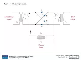
Bandpass Limiter • A device that imposes hard limiting on a signal and contains a filter that suppresses the unwanted products (harmonics) of the limiting process. • Input Signal • Output of bandpass limiter • Bandpass filter • Remove the amplitude variations
Ratio Detector • Foster-Seeley/phase shift discriminator • uses a double-tuned transformer to convert the instantaneous frequency variations of the FM input signal to instantaneous amplitude variations. These amplitude variations are rectified to provide a DC output voltage which varies in amplitude and polarity with the input signal frequency. • Example • Ratio detector • Modified Foster-Seeley discriminator, not response to AM, but 50%
FM Demodulator PLL • Phase-locked loop (PLL) • A closed-loop feedback control circuit, make a signal in fixed phase (and frequency) relation to a reference signal • Track frequency (or phase) variation of inputs • Or, change frequency (or phase) according to inputs • PLL can be used for both FM modulator and demodulator • Just as Balanced Modulator IC can be used for most amplitude modulations and demodulations
PLL FM • Remember the following relations • Si=Acos(wct+1(t)), Sv=Avcos(wct+c(t)) • Sp=0.5AAv[sin(2wct+1+c)+sin(1-c)] • So=0.5AAvsin(1-c)=AAv(1-c)
Superheterodyne Receiver • Radio receiver’s main function • Demodulation get message signal • Carrier frequency tuning select station • Filtering remove noise/interference • Amplification combat transmission power loss • Superheterodyne receiver • Heterodyne: mixing two signals for new frequency • Superheterodyne receiver: heterodyne RF signals with local tuner, convert to common IF • Invented by E. Armstrong in 1918.
Advantage of superheterodyne receiver • A signal block (of circuit) can hardly achieve all: selectivity, signal quality, and power amplification • Superheterodyne receiver deals them with different blocks • RF blocks: selectivity only • IF blocks: filter for high signal quality, and amplification, use circuits that work in only a constant IF, not a large band
FM Broadcasting • The frequency of an FM broadcast station is usually an exact multiple of 100 kHz from 87.5 to 108.5 MHz . In most of the Americas and Caribbean only odd multiples are used. • fm=15KHz, f=75KHz, =5, B=2(fm+f)=180kHz • Pre-emphasis and de-emphasis • Random noise has a 'triangular' spectral distribution in an FM system, with the effect that noise occurs predominantly at the highest frequencies within the baseband. This can be offset, to a limited extent, by boosting the high frequencies before transmission and reducing them by a corresponding amount in the receiver. • Block diagram and spectrum • Relation of stereo transmission and monophonic transmission
Fc=19KHz.(a) Multiplexer in transmitter of FM stereo. (b) Demultiplexer in receiver of FM stereo. FM Stereo Multiplexing Backward compatible For non-stereo receiver
TV FM broadcasting • fm=15KHz, f=25KHz, =5/3, B=2(fm+f)=80kHz • Center fc+4.5MHz • Eye cells structure
Project 1 • Project 1 • AM/FM/Real voice • Due 10/1/12