Download
1 / 43
430 likes | 444 Views
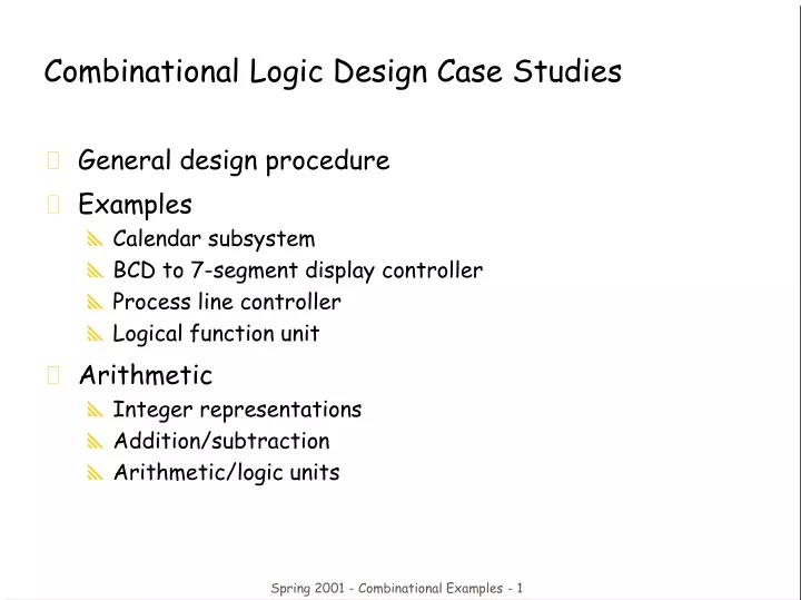
Combinational Logic Design Case Studies. General design procedure Examples Calendar subsystem BCD to 7-segment display controller Process line controller Logical function unit Arithmetic Integer representations Addition/subtraction Arithmetic/logic units.

E N D
Combinational Logic Design Case Studies • General design procedure • Examples • Calendar subsystem • BCD to 7-segment display controller • Process line controller • Logical function unit • Arithmetic • Integer representations • Addition/subtraction • Arithmetic/logic units Spring 2001 - Combinational Examples - 1
General Design Procedure for Combinational Logic • 1. Understand the Problem • What is the circuit supposed to do? • Write down inputs (data, control) and outputs • Draw block diagram or other picture • 2. Formulate the Problem using a Suitable Design Representation • Truth table or waveform diagram are typical • May require encoding of symbolic inputs and outputs • 3. Choose Implementation Target • ROM, PAL, PLA • Mux, decoder and OR-gate • Discrete gates • 4. Follow Implementation Procedure • K-maps for two-level, multi-level • Design tools and hardware description language (e.g., Verilog) Spring 2001 - Combinational Examples - 2
Calendar Subsystem • Determine number of days in a month (to control watch display) • Used in controlling thedisplay of a wrist-watchLCD screen • Inputs: month, leap yearflag • Outputs: number of days • Use softwareimplementationto help understandthe problem • integer number_of_days ( month, leap_year_flag) { • switch (month) { • case 1: return (31); • case 2: if (leap_year_flag == 1) • then return (29) else return (28); • case 3: return (31); • case 4: return (30); • case 5: return (31); • case 6: return (30); • case 7: return (31); • case 8: return (31); • case 9: return (30); • case 10: return (31); • case 11: return (30); • case 12: return (31); • default: return (0); • } • } Spring 2001 - Combinational Examples - 3
month leap 28 29 30 310000 – – – – –0001 – 0 0 0 10010 0 1 0 0 00010 1 0 1 0 00011 – 0 0 0 10100 – 0 0 1 00101 – 0 0 0 10110 – 0 0 1 00111 – 0 0 0 11000 – 0 0 0 11001 – 0 0 1 01010 – 0 0 0 11011 – 0 0 1 01100 – 0 0 0 11101 – – – – –111– – – – – –month leap 28 29 30 310000 – – – – –0001 – 0 0 0 10010 0 1 0 0 00010 1 0 1 0 00011 – 0 0 0 10100 – 0 0 1 00101 – 0 0 0 10110 – 0 0 1 00111 – 0 0 0 11000 – 0 0 0 11001 – 0 0 1 01010 – 0 0 0 11011 – 0 0 1 01100 – 0 0 0 11101 – – – – –111– – – – – – month leap 28 29 30 31 Formalize the Problem • Encoding: • Binary number for month: 4 bits • 4 wires for 28, 29, 30, and 31one-hot – only one true at any time • Block diagram: Spring 2001 - Combinational Examples - 4
month leap 28 29 30 310000 – – – – –0001 – 0 0 0 10010 0 1 0 0 00010 1 0 1 0 00011 – 0 0 0 10100 – 0 0 1 00101 – 0 0 0 10110 – 0 0 1 00111 – 0 0 0 11000 – 0 0 0 11001 – 0 0 1 01010 – 0 0 0 11011 – 0 0 1 01100 – 0 0 0 11101 – – – – –111– – – – – –month leap 28 29 30 310000 – – – – –0001 – 0 0 0 10010 0 1 0 0 00010 1 0 1 0 00011 – 0 0 0 10100 – 0 0 1 00101 – 0 0 0 10110 – 0 0 1 00111 – 0 0 0 11000 – 0 0 0 11001 – 0 0 1 01010 – 0 0 0 11011 – 0 0 1 01100 – 0 0 0 11101 – – – – –111– – – – – – Choose Implementation Targetand Perform Mapping • Discrete gates • 28 = • 29 = • 30 = • 31 = • Can translate to S-o-Por P-o-S m8’ m4’ m2 m1’ leap’ m8’ m4’ m2 m1’ leap m8’ m4 m1’ + m8 m1 m8’ m1 + m8 m1’ Spring 2001 - Combinational Examples - 5
c0 c1 c5 c6 c4 c2 c3 BCD to 7-segment display controller • Understanding the problem • Input is a 4 bit bcd digit (A, B, C, D) • Output is the control signals for the display (7 outputs C0 – C6) • Block diagram c0 c1 c2 c3 c4 c5 c6 BCD to 7–segmentcontrol signaldecoder A B C D Spring 2001 - Combinational Examples - 6
Formalize the problem • Truth table • Show don't cares • Choose implementationtarget • If ROM, we are done • Don't cares imply PAL/PLAmay be attractive • Follow implementationprocedure • Minimization using K-maps A B C D C0 C1 C2 C3 C4 C5 C6 0 0 0 0 1 1 1 1 1 1 0 0 0 0 1 0 1 1 0 0 0 0 0 0 1 0 1 1 0 1 1 0 1 0 0 1 1 1 1 1 1 0 0 1 0 1 0 0 0 1 1 0 0 1 1 0 1 0 1 1 0 1 1 0 1 1 0 1 1 0 1 0 1 1 1 1 1 0 1 1 1 1 1 1 0 0 0 0 1 0 0 0 1 1 1 1 1 1 1 1 0 0 1 1 1 1 0 0 1 1 1 0 1 – – – – – – – – 1 1 – – – – – – – – – Spring 2001 - Combinational Examples - 7
A A A A A A A 1 0 X 1 0 1 X 0 1 0 X X 1 1 X X 1 1 X 1 1 0 X 1 1 1 X X 1 0 X X 1 1 X 1 0 1 X 1 0 0 X X 0 1 X X 1 0 X 1 0 0 X 0 0 0 X X 1 1 X X 1 1 X 1 1 1 X 1 1 1 X X 0 1 X X 0 1 X 1 0 1 X 1 1 0 X X 1 1 X X 1 0 X 1 0 1 X 1 1 1 X X 1 1 X X D D D D D D D C C C C C C C B B B B B B B Implementation as Minimized Sum-of-Products • 15 unique product terms when minimized individually C0 = A + B D + C + B' D' C1 = C' D' + C D + B' C2 = B + C' + D C3 = B' D' + C D' + B C' D + B' C C4 = B' D' + C D' C5 = A + C' D' + B D' + B C' C6 = A + C D' + B C' + B' C Spring 2001 - Combinational Examples - 8
A A 1 1 X 1 1 1 X 1 1 1 X X 0 1 X X 1 1 X 1 1 1 X 1 1 1 X X 0 1 X X D D C C B B Implementation as Minimized S-o-P (cont'd) • Can do better • 9 unique product terms (instead of 15) • Share terms among outputs • Each output not necessarily in minimized form C2 C2 C0 = A + B D + C + B' D' C1 = C' D' + C D + B' C2 = B + C' + D C3 = B' D' + C D' + B C' D + B' C C4 = B' D' + C D' C5 = A + C' D' + B D' + B C' C6 = A + C D' + B C' + B' C C0 = B C' D + C D + B' D' + B C D' + AC1 = B' D + C' D' + C D + B' D'C2 = B' D + B C' D + C' D' + C D + B C D'C3 = B C' D + B' D + B' D' + B C D'C4 = B' D' + B C D'C5 = B C' D + C' D' + A + B C D'C6 = B' C + B C' + B C D' + A Spring 2001 - Combinational Examples - 9
A B C D BC' B'C B'D BC'D C'D' CD B'D' A BCD' C0 C1 C2 C3 C4 C5 C6 C7 PLA implementation Spring 2001 - Combinational Examples - 10
PAL Implementation • Limit of 4 Product Terms per Output • Decomposition of functions with larger number of terms • Do not share terms in PAL anyway(although there are some with some shared terms) • Decompose into multi-level logic (hopefully with CAD support) • Find common sub-expressions among functions C2 = B + C' + D C2 = B' D + B C' D + C' D' + C D + B C D' C2 = B' D + B C' D + C' D' + W W = C D + B C D' need another input and another output C0 = C3 + A' B X' + A D Y C1 = Y + A' C5' + C' D' C6 C2 = C5 + A' B' D + A' C D C3 = C4 + B D C5 + A' B' X' C4 = D' Y + A' C D' C5 = C' C4 + A Y + A' B X C6 = A C4 + C C5 + C4'C5 + A' B' C X = C' + D' Y = B' C' Spring 2001 - Combinational Examples - 11
Production Line Control • Rods of varying length (+/-10%) travel on conveyor belt • Mechanical arm pushes rods within spec (+/-5%) to one side • Second arm pushes rods too long to other side • Rods that are too short stay on belt • 3 light barriers (light source + photocell) as sensors • Design combinational logic to activate the arms • Understanding the problem • Inputs are three sensors • Outputs are two arm control signals • Assume sensor reads "1" when tripped, "0" otherwise • Call sensors A, B, C Spring 2001 - Combinational Examples - 12
A spec- 5% TooShort TooLong WithinSpec spec+ 5% B C Sketch of Problem • Position of Sensors • A to B distance = specification – 5% • A to C distance = specification + 5% Spring 2001 - Combinational Examples - 13
Formalize the problem • Truth Table • Show don't cares logic implementation now straightforwardjust use three 3-input AND gates"too short" = AB'C' (only first sensor tripped)"in spec" = A B C' (first two sensors tripped) "too long" = A B C (all three sensors tripped) A B C Function0 0 0 do nothing0 0 1 do nothing0 1 0 do nothing0 1 1 do nothing1 0 0 too short1 0 1 don't care1 1 0 in spec1 1 1 too long Spring 2001 - Combinational Examples - 14
Logical Function Unit • Multi-purpose Function Block • 3 control inputs to specify operation to perform on operands • 2 data inputs for operands • 1 output of the same bit-width as operands C0 C1 C2 Function Comments0 0 0 1 always 10 0 1 A + B logical OR0 1 0 (A • B)' logical NAND0 1 1 A xor B logical xor1 0 0 A xnor B logical xnor1 0 1 A • B logical AND1 1 0 (A + B)' logical NOR1 1 1 0 always 0 3 control inputs: C0, C1, C22 data inputs: A, B1 output: F Spring 2001 - Combinational Examples - 15
C0 C1 C2 A B F 0 0 0 0 0 1 0 0 0 0 1 1 0 0 0 1 0 1 0 0 0 1 1 1 0 0 1 0 0 0 0 0 1 0 1 1 0 0 1 1 0 1 0 0 1 1 1 1 0 1 0 0 0 1 0 1 0 0 1 1 0 1 0 1 0 1 0 1 0 1 1 0 0 1 1 0 0 0 0 1 1 0 1 1 0 1 1 1 0 1 0 1 1 1 1 0 1 0 0 0 0 1 1 0 0 0 1 0 1 0 0 1 0 0 1 0 0 1 1 1 1 0 1 0 0 0 1 0 1 0 1 0 1 0 1 1 0 0 1 0 1 1 1 1 1 1 0 0 0 1 1 1 0 0 1 0 1 1 0 1 0 0 1 1 0 1 1 0 1 1 1 0 0 0 1 1 1 0 1 0 1 1 1 1 0 0 1 1 1 1 1 0 01234567 AB F AB 8:1 MUX AB S2 S1 S0 C0 C1 C2 Formalize the Problem choose implementation technology5-variable K-map to discrete gatesmultiplexer implementation 10 Spring 2001 - Combinational Examples - 16
Arithmetic Circuits • Excellent Examples of Combinational Logic Design • Time vs. Space Trade-offs • Doing things fast may require more logic and thus more space • Example: carry lookahead logic • Arithmetic and Logic Units • General-purpose building blocks • Critical components of processor datapaths • Used within most computer instructions Spring 2001 - Combinational Examples - 17
Number Systems • Representation of positive numbers is the same in most systems • Major differences are in how negative numbers are represented • Representation of negative numbers come in three major schemes • Sign and magnitude • 1s complement • 2s complement • Assumptions • We'll assume a 4 bit machine word • 16 different values can be represented • Roughly half are positive, half are negative Spring 2001 - Combinational Examples - 18
–7 +0 +1 0000 –6 1111 1110 0001 –5 +2 1101 0010 –4 +3 1100 0011 –3 1011 0100 +4 1010 0101 –2 +5 1001 0110 +6 –1 1000 0111 –0 +7 Sign and Magnitude • One bit dedicate to sign(positive or negative) • sign: 0 = positive (or zero), 1 = negative • Rest represent the absolutevalue or magnitude • three low order bits: 0 (000)thru 7 (111) • Range for n bits • +/– 2n–1 –1 (two representationsfor 0) • Cumbersome addition/subtraction • must compare magnitudesto determine sign of result 0 100 = + 41 100 = – 4 Spring 2001 - Combinational Examples - 19
1s Complement • If N is a positive number, then the negative of N ( its 1s complement or N' ) is N' = (2n– 1) – N • Example: 1s complement of 7 • Shortcut: simply compute bit-wise complement ( 0111 -> 1000 ) 4 2 = 10000 1 = 00001 2 –1 = 1111 7 = 0111 1000 = –7 in 1s complement form 4 Spring 2001 - Combinational Examples - 20
–0 +0 +1 –1 0000 1111 1110 0001 –2 +2 1101 0010 –3 +3 1100 0011 –4 1011 0100 +4 1010 0101 –5 +5 1001 0110 1000 0111 +6 –6 +7 –7 1s complement (cont'd) • Subtraction implemented by 1s complement and then addition • Two representations of 0 • Causes some complexities in addition • High-order bit can act as sign bit 0 100 = + 41 011 = – 4 Spring 2001 - Combinational Examples - 21
–1 +0 +1 –2 0000 1111 1110 0001 –3 +2 1101 0010 –4 +3 1100 0011 –5 1011 0100 +4 1010 0101 –6 +5 1001 0110 1000 0111 +6 –7 +7 –8 2s Complement • 1s complement with negative numbers shifted one position clockwise • Only one representation for 0 • One more negative number than positive number • High-order bit can act as sign bit 0 100 = + 41 100 = – 4 Spring 2001 - Combinational Examples - 22
2s complement (cont’d) • If N is a positive number, then the negative of N ( its 2s complement or N* ) is N* = 2n – N • Example: 2s complement of 7 • Example: 2s complement of –7 • Shortcut: 2s complement = bit-wise complement + 1 • 0111 -> 1000 + 1 -> 1001 (representation of -7) • 1001 -> 0110 + 1 -> 0111 (representation of 7) 4 2 = 10000 7 = 0111 1001 = repr. of –7 subtract 4 2 = 10000 –7 = 1001 0111 = repr. of 7 subtract Spring 2001 - Combinational Examples - 23
2s Complement Addition and Subtraction • Simple Addition and Subtraction • Simple scheme makes 2s complement the virtually unanimous choice for integer number systems in computers – 4 + (– 3) – 7 1100 1101 11001 4 + 3 7 0100 0011 0111 4 – 3 1 0100 1101 10001 – 4 + 3 – 1 1100 0011 1111 Spring 2001 - Combinational Examples - 24
Why Can the Carry-out be Ignored? • Can't ignore it completely • Needed to check for overflow (see next two slides) • When there is no overflow, carry-out may be true but can be ignored – M + N when N > M:M* + N = (2n – M) + N = 2n + (N – M)ignoring carry-out is just like subtracting 2n – M + – N where N + M 2n–1(– M) + (– N) = M* + N* = (2n– M) + (2n– N) = 2n – (M + N) + 2nignoring the carry, it is just the 2s complement representation for – (M + N) Spring 2001 - Combinational Examples - 25
–1 +0 –1 +0 +1 +1 –2 –2 0000 0000 1111 1111 1110 1110 0001 0001 –3 –3 +2 +2 1101 0010 1101 0010 –4 –4 +3 +3 1100 0011 1100 0011 –5 –5 1011 1011 0100 0100 +4 +4 1010 1010 0101 0101 –6 –6 +5 +5 1001 1001 0110 0110 1000 0111 +6 1000 0111 +6 –7 –7 +7 +7 –8 –8 Overflow in 2s Complement Addition/Subtraction • Overflow conditions • Add two positive numbers to get a negative number • Add two negative numbers to get a positive number 5 + 3 = –8 –7 – 2 = +7 Spring 2001 - Combinational Examples - 26
Overflow Conditions • Overflow when carry into sign bit position is not equal to carry-out 0 1 1 1 0 1 0 10 0 1 1 1 0 0 0 1 0 0 0 1 0 0 1 1 1 1 01 0 1 1 1 5 3 – 8 – 7 – 2 7 overflow overflow 0 0 0 0 0 1 0 1 0 0 1 0 0 1 1 1 1 1 1 1 1 1 0 1 1 0 1 11 1 0 0 0 5 2 7 – 3 – 5 – 8 no overflow no overflow Spring 2001 - Combinational Examples - 27
Ai Bi Sum Cout0 0 0 00 1 1 01 0 1 01 1 1 1 Ai Bi Cin Sum Cout0 0 0 0 00 0 1 1 00 1 0 1 00 1 1 0 11 0 0 1 01 0 1 0 11 1 0 0 11 1 1 1 1 Circuits for Binary Addition • Half adder (add 2 1-bit numbers) • Sum = Ai' Bi + Ai Bi' = Ai xor Bi • Cout = Ai Bi • Full adder (carry-in to cascade for multi-bit adders) • Sum = Ci xor A xor B • Cout = B Ci + A Ci + A B = Ci (A + B) + A B Spring 2001 - Combinational Examples - 28
A B S Cin A B Cin Cout A B A xor B A xor B xor Cin Sum A Sum Sum HalfAdder HalfAdder B A B Cin (A xor B) Cout Cout Cin Cout Full adder implementations • Standard approach • 6 gates • 2 XORs, 2 ANDs, 2 ORs • Alternative implementation • 5 gates • half adder is an XOR gate and AND gate • 2 XORs, 2 ANDs, 1 OR Cout = A B + Cin (A xor B) = A B + B Cin + A Cin Spring 2001 - Combinational Examples - 29
A2 B2 B2' A1 B1 B1' A0 B0 B0' A3 B3 B3' Sel Sel Sel Sel 0 1 0 1 0 1 0 1 B B B A A A A B Add'Subtract Cout Cin Cout Cin Cout Cin Cout Cin Sum Sum Sum Sum S3 S2 S1 S0 Overflow Adder/Subtractor • Use an adder to do subtraction thanks to 2s complement representation • A – B = A + (– B) = A + B' + 1 • Control signal selects B or 2s complement of B Spring 2001 - Combinational Examples - 30
Cin 4 stage adder @N+1 @0 @0 @1 A B A0 S0 @2 B0 C1 @2 Cin @N Cout @N+2 @0 @0 A B A1 @1 S1 @3 B1 C2 @4 late arriving signal two gate delays to compute Cout A2 S2 @5 B2 C3 @6 A3 S3 @7 B3 Cout @8 Ripple-Carry Adders • Critical Delay • The propagation of carry from low to high order stages Spring 2001 - Combinational Examples - 31
Ripple-Carry Adders (cont’d) • Critical delay • The propagation of carry from low to high order stages • 1111 + 0001 is the worst case addition • Carry must propagate through all bits Spring 2001 - Combinational Examples - 32
Carry-Lookahead Logic • Carry generate: Gi = Ai Bi • Must generate carry when A = B = 1 • Carry propagate: Pi = Ai xor Bi • Carry-in will equal carry-out here • Sum and Cout can be re-expressed in terms of generate/propagate: • Si = Ai xor Bi xor Ci = Pi xor Ci • Ci+1 = Ai Bi + Ai Ci + Bi Ci = Ai Bi + Ci (Ai + Bi) = Ai Bi + Ci (Ai xor Bi) = Gi + Ci Pi Spring 2001 - Combinational Examples - 33
Carry-Lookahead Logic (cont’d) • Re-express the carry logic as follows: • C1 = G0 + P0 C0 • C2 = G1 + P1 C1 = G1 + P1 G0 + P1 P0 C0 • C3 = G2 + P2 C2 = G2 + P2 G1 + P2 P1 G0 + P2 P1 P0 C0 • C4 = G3 + P3 C3 = G3 + P3 G2 + P3 P2 G1 + P3 P2 P1 G0 + P3 P2 P1 P0 C0 • Each of the carry equations can be implemented with two-level logic • All inputs are now directly derived from data inputs and not from intermediate carries • this allows computation of all sum outputs to proceed in parallel Spring 2001 - Combinational Examples - 34
Ai Pi @ 1 gate delay Bi Si @ 2 gate delays Ci Gi @ 1 gate delay C0 C0 C0 P0 P0 P0 C1 P1 P1 G0 P2 P2 P3 G0 P1 G0 C0 P2 P1 P0 P2 P1 G1 C3 P3 P2 G0 G1 C2 P1 P2 G2 P3 G1 C4 G2 P3 G3 Carry-Lookahead Implementation • Adder with propagate and generate outputs increasingly complexlogic for carries Spring 2001 - Combinational Examples - 35
Cin Cin A0 S0 @2 B0 S0 @2 A0 C1 @3 C1 @2 B0 A1 S1 @4 B1 S1 @3 A1 C2 @3 C2 @4 B1 A2 S2 @4 B2 S2 @5 A2 C3 @3 C3 @6 B2 A3 S3 @4 B3 A3 S3 @7 C4 @3 C4 @3 B3 Cout @8 Carry-Lookahead Implementation (cont’d) • Carry-lookahead logic generates individual carries • Sums computed much more quickly in parallel • However, cost of carry logic increases with more stages Spring 2001 - Combinational Examples - 36
4 4 4 4 4 4 4 4 4-bit Adder 4-bit Adder 4-bit Adder 4-bit Adder A[15-12] B[15-12] A[11-8] B[11-8] A[7-4] B[7-4] A[3-0] B[3-0] C12 C8 C4 C0 P G P G P G P G @0 4 4 4 4 S[15-12] S[11-8] S[7-4] S[3-0] @8 @8 @7 @4 @3 @2 @2 @3 @2 @3 @2 @3 @5 @5 @4 P3 G3 P2 G2 C2 P1 G1 C1 P0 G0 C3 C0 C16 C0 C4 Lookahead Carry Unit @4 @0 P3-0 G3-0 @3 @5 Carry-Lookahead Adderwith Cascaded Carry-Lookahead Logic • Carry-lookahead adder • 4 four-bit adders with internal carry lookahead • Second level carry lookahead unit extends lookahead to 16 bits Spring 2001 - Combinational Examples - 37
4-bit adder[7:4] C8 1 adderhigh C8 0 4-bit adder[7:4] adder low 1 0 1 0 1 0 1 0 1 0 C0 C4 4-Bit Adder[3:0] five2:1 mux S6 S1 C8 S7 S5 S4 S3 S2 S0 Carry-Select Adder • Redundant hardware to make carry calculation go faster • Compute two high-order sums in parallel while waiting for carry-in • One assuming carry-in is 0 and another assuming carry-in is 1 • Select correct result once carry-in is finally computed Spring 2001 - Combinational Examples - 38
Arithmetic Logic Unit Design Specification M = 0, logical bitwise operations S10011 S00101 FunctionFi = AiFi = not AiFi = Ai xor BiFi = Ai xnor Bi Commentinput Ai transferred to outputcomplement of Ai transferred to outputcompute XOR of Ai, Bicompute XNOR of Ai, Bi M = 1, C0 = 0, arithmetic operations 0011 0101 F = AF = not AF = A plus BF = (not A) plus B input A passed to outputcomplement of A passed to outputsum of A and Bsum of B and complement of A M = 1, C0 = 1, arithmetic operations 0011 0101 F = A plus 1F = (not A) plus 1F = A plus B plus 1F = (not A) plus B plus 1 increment Atwos complement of Aincrement sum of A and BB minus A logical and arithmetic operationsnot all operations appear useful, but "fall out" of internal logic Spring 2001 - Combinational Examples - 39
M011 S1001100110011 S0010101010101 CiXXXXXXXXXXXX000000000000111111111111 Ai0101001100110101001100110 10100110011 BiXXXX01010101XXXX01010101XXXX01010101 Fi011001101001011001101001100110010110 Ci+1XXXXXXXXXXXXXXXX00010100011001111101 Arithmetic Logic Unit Design (cont’d) • Sample ALU – truth table Spring 2001 - Combinational Examples - 40
\S1 \Bi [35] M Ci Ci [33] \Co Ci Co [30] M S1 Bi [30] [33] [33] Fi [33] \Co M [30] Ci [35] [30] S0 Ai [30] \Co \[30] \[35] Arithmetic Logic Unit Design (cont’d) • Sample ALU – multi-level discrete gate logic implementation 12 gates Spring 2001 - Combinational Examples - 41
S1 Ai Bi S0 Ci M X1 A1 A2 X2 A3 A4 X3 O1 Ci+1 Fi Arithmetic Logic Unit Design (cont’d) • Sample ALU – clever multi-level implementation • first-level gates • use S0 to complement Ai S0 = 0 causes gate X1 to pass Ai S0 = 1 causes gate X1 to pass Ai' • use S1 to block Bi S1 = 0 causes gate A1 to make Bi go forward as 0 (don't want Bi for operations with just A) S1 = 1 causes gate A1 to pass Bi • use M to block Ci M = 0 causes gate A2 to make Ci go forward as 0 (don't want Ci for logical operations) M = 1 causes gate A2 to pass Ci • other gates • for M=0 (logical operations, Ci is ignored) • Fi = S1 Bi xor (S0 xor Ai) • = S1'S0' ( Ai ) + S1'S0 ( Ai' ) + S1 S0' ( Ai Bi' + Ai' Bi ) + S1 S0 ( Ai' Bi' + Ai Bi ) • for M=1 (arithmetic operations) • Fi = S1 Bi xor ( ( S0 xor Ai ) xor Ci ) = • Ci+1 = Ci (S0 xor Ai) + S1 Bi ( (S0 xor Ai) xor Ci ) = • just a full adder with inputs S0 xor Ai, S1 Bi, and Ci Spring 2001 - Combinational Examples - 42
Summary for Examples of Combinational Logic • Combinational logic design process • Formalize problem: encodings, truth-table, equations • Choose implementation tech (ROM, PAL, PLA, discrete gates) • Implement by following the design procedure for that technology • Binary number representation • Positive numbers the same • Difference is in how negative numbers are represented • 2s complement easiest to handle: one representation for zero, slightly complicated complementation, simple addition • Circuits for binary addition • Basic half-adder and full-adder • Carry lookahead logic • Carry-select • ALU Design • Specification, implementation Spring 2001 - Combinational Examples - 43