Download
1 / 35
350 likes | 433 Views
Simultaneous Time Slack Budgeting and Retiming for Dual-Vdd FPGA Power Reduction. Yu Hu 1 , Yan Lin 1 , Lei He 1 and Tim Tuan 2 1 EE Department, UCLA 2 Xilinx Research Lab Presented by Yu Hu Partially supported by NSF. Address comments to lhe@ee.ucla.edu. Outline.

E N D
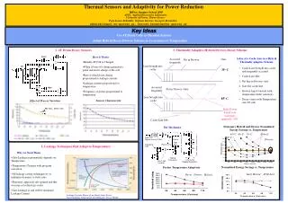
Simultaneous Time Slack Budgeting and Retiming for Dual-Vdd FPGA Power Reduction Yu Hu1, Yan Lin1, Lei He1 and Tim Tuan2 1EE Department, UCLA 2Xilinx Research Lab Presented by Yu Hu Partially supported by NSF. Address comments to lhe@ee.ucla.edu
Outline • Background, Motivation and Problem Formulation • Chip-level Vdd-level Assignment Algorithm [for mixed length wire segments] • Simultaneous Vdd Level Assignment and Retiming • Experimental Results • Conclusions
Background • Existing FPGAs are power inefficient compared to ASICs. • Interconnect is the dominant component of FPGA power dissipation (dynamic and leakage).[Li, TCAD‘05] • Power aware FPGA architectures and CAD algorithms have been studied extensively. • CAD algorithms to minimize power-delay product[Lamoureux, ICCAD’03] • Configuration inversion for leakage reduction[Anderson, FPGA’04] • Vdd-programmable FPGA logic blocks [Li, FPGA’04] [Li, DAC’04] • Vdd-programmable FPGA interconnects [Li, ICCAD’04] [Gayasen, FPL’04] [Anderson, ICCAD’04] [Lin, DAC’05]
Vdd Programmable Interconnect Arch. • Island style and mixed wire segment length. • Routing switch/connection block(Two PMOS power transistors M3 and M4 are inserted between the tri-state buffer and VddH, VddL power rails, respectively.) [Li, ICCAD’04] • Level converter free in routing tree(Guarantee that no VddL switch drives VddH switches.) with LEAST area and power penalty[Lin, TCAD’06].
Limitation of Existing Approaches • The most recent work [Lin, DAC'05] for programmable dual-Vdd FPGA considers timing slack budgeting to maximize power reduction • Uniform wire segment length was assumed, and can not be extended to mixed wire segment. • Vdd level assignment was performed in combinational sub-circuits. • Simultaneous retiming and timing budgeting has been studied to reduce area or improve performance.[Yeh, DAC'03] [Yeh, ICCAD'03] • Power reduction has not been considered. • Post-layout flip-flop binding constraints were not addressed.
Call for Simultaneous Vdd Assignment and Retiming • [Lin, DAC'05] performs Vdd level assignment in the combinational sub-circuit, which limits the searching space. • Simultaneous retiming and Vdd assignment explores larger searching space to extract more useful timing slack for VddL switches insertion. 2 units slack needed for a VddL switch insertion Interconnect Delay Timing Slack Combinational Assign Sequential Assignment All VddH Switches ! Movable with Retiming! VddL Switch Inserted !
Synthesis / Placement / routing CLB level V dd assignment Min - clock retiming Interconnect Vdd assignment Simultaneous retiming and interconnect Vdd assignment Global refinement Major Contributions Power-aware post-layout re-synthesis processes: Sequential vs. Simultaneous Vdd level assignment for mixed wire segments FPGAs. 53% interconnect power reduction is achieved compared to single Vdd designs. Simultaneous retiming and interconnect Vdd assignment with flip-flop binding constraints. Up to 20% further interconnect power reduction is achieved compared to sequential flow.
Problem Formulations [ Dual-Vdd Level Assignment Problem ] Given: placement and routing results of a FPGA design Find: A Vdd-level assignment to each interconnect switch Objective: Minimize interconnect (dynamic and leakage) power Constraints: • Meet the delay target Tspec • Vdd-level converters are inserted ONLY at CLB inputs/outputs [ Simultaneous Retiming and Dual-Vdd Level Assignment Problem ] Same to Dual-Vdd level assignment problem in addition to: • Retiming as an extra design freedom • Satisfy post-layout flip-flop binding constraints.
Outline • Background, Motivation and Problem Formulation • Chip-level Vdd-level Assignment Algorithm [for mixed length wire segments] • Interconnect Power Reduction Estimation • LP Based Vdd-level Assignment Algorithm • Simultaneous Vdd Level Assignment and Retiming • Experimental Results • Conclusions
Delay and Power Model for Interconnect • Delay Model • Intrinsic delay and effective driving resistance of switch has been pre-characterized using SPICE. • Elmore delay is used to calculate routing delay. • Interconnect Power Model • Dynamic power Pd(Vddjj)=0.5fclk*C*Vddjj2 • Leakage power Pl(Vddjj) is pre-characterized using SPICE • Interconnect power reduction estimation is the essential part of dual-Vdd assignment algorithm.
VddL possibility for switches Power reduction estimation Vdd assignment base on estimation Timing Slack assigned at sinks b4 b4 b3 b3 b1 b1 b2 b2 S1=1 S1=1 S2=3 S2=3 Review of Vdd Level Assignment Algorithm[Lin, DAC'05] Interconnect power reduction estimation Problem remained: How to calculate VddL possibility for mixed wire segment? The net-level bottom-up Vdd assignment guarantees the legalization of final solutions. [Lin, DAC’05] Leverage all extra slack with VddL switches [Lin, DAC’05]
b4, 16x b1, 8x b3, 16x S1=6 b2, 8x S2=10 VddL Possibility Calculation • Represent timing slack in number of switches: • si = Li * ( Si / Di ) • si is the number of VddL switches can be inserted in the path from source to jth sink in the routing tree. • Li is the number of switches along this path. • si: how many switches can be turned to VddL along source-to-sink-i path for the given timing slack Si. • VddL possiblity for switch j at sink i based on load capacity: • f(i,j) = si* (cij / Ci) • Key idea: distribute timing slack to each switch based on cap. f(2,2) = 1 f(2,3) = 1 f(2,4) = 1/2 L2 = 3 D2 = 12 s2 = 3*(10/12)=5/2
Power Reduction Estimation for Mixed Wire Segments • The lower bound estimation [Y. Lin, DAC'05] for interconnect power reduction is no longer valid for mixed wire segments. • Our solution: develop the upper bound estimation of VddL switch number • Consistent upper bound of power reduction • Remove the non-linear term "min" and the corresponding extra LP constraints from lower bound estimation 1.7 slack left -1.8 needed! Only 1.0 VddL switch assignment b1, 16x, need 1.8 slack fn(i,1) = 0.9 fn(i,2) = 0.5 lower bound of VddL switches = 0.9 + .5 = 1.4 b2, 8x, need 1.0 slack Consume 1.0 S = 2.7 S = 2.7 Problem here: Lower bound > actual number! Sum up all VddL possibility
Dynamic power reduction upper bound Leakage power reduction upper bound LP formulation for dual-Vdd Level Assignment • Basic timing constraints • Slack constraints • Objective function Arrival time for prim-output Arrival time for prim-input Arrival time constraints Slack upper bound Slack constraints Slack non-negative
Outline • Motivation • Problem Formulations • Chip-level Vdd-level Assignment Algorithm [for mixed length wire segments] • Simultaneous Vdd Level Assignment and Retiming • MILP formulation for retiming FPGA circuits • Extra constraints for post-layout FPGA retiming • Link between MILP retiming to timing budgeting • Experimental Results • Conclusions
Retiming for FPGA • Retiming graph is a directed cyclic graph. • Given the retiming graph G=(V, E), a retiming is an integer-valued vertex-labelingr: V→ Z. • A weight is w(u,v) associated with edge e(u,v) denotes the number of FFs in that edge. • After retiming (re-labeling of vertices): w'(u,v) = w(u,v) + r(v) – r(u) Retiming
Link between MILP retiming & timing budgeting • Extend MILP formulation in [Leiserson, Algorithmica’91] to link arrival time with retiming labeling • Timing slack in edge (u,v) is represented by • Timing slack in connection from sink Sk to the source of routing tree Ri The real value a(v) assigned in node v is its arrival time after retiming linearize R(v) = r(v) + a(v) /c,
Retiming Constraints 1: Placement and Flip-Flop Binding Constraints • Keep both placement and routing unchanged after retiming. • No FFs in global interconnect (inter-CLB) • No FFs in local interconnect (intra-CLB and inter-SLICE) • Within a single SLICE, only FF_NODE → SUBBLK_OPIN edges allow FF insertion. • Extra constraints in MILP formulation: No way to assign this FF in any SLICE physically! The only timing edge that can insert FFs FF# can be further reduced!
Retiming Constraints 2:LUT Delay and FF Setup &Hold Time Constraints • Delay constraints for timing edges within SLICE: FF hold time FF setup time + LUT delay LUT delay FF# in edge (e)
Outline • Motivation • Problem Formulations • Chip-level Vdd-level Assignment Algorithm [for mixed length wire segments] • Simultaneous Vdd Level Assignment and Retiming • Experimental Results • Dual-Vdd Assignment for FPGAs with Mixed Wire Segments • Simultaneous Vdd Level Assignment and Retiming • A runtime Efficient Post-Layout Re-Synthesis CAD Flow • Conclusions
Experimental Setting • Cluster-based Island Style FPGA Structure • Size-10 cluster and size-4 LUT • 100% buffered interconnects, subset switch block • 60% length-4 and 40% length-8l wire segments • 25x buffer for length-4 and 10x buffer for length-8 • ITRS 100nm technology, 1.3v for VddH and 0.8v for VddL • Use VPR [Betz-Rose-Marquardt] for placement and routing • Use fpgaEva-LP2 [Lin et al, FPGA’05] for power calculation • Considering short-circuit power, glitch power and input vector • 8% average error compared to SPICE simulation • 10 biggest sequential MCNC benchmarks are tested • Use mosek [student license, www.mosek.com] to solveLP and MILP
Experimental Results: Dual-Vdd Assignment for FPGAs with Mixed Wire Segments • EdTLC-LP algorithm achieves 85% VddL assignment. • EdTLC-LP algorithm achieves 53% interconnect power reduction for mixed length interconnect wire on average.
Experimental Results – Simultaneous vs. Sequential • Simultaneous Retiming and Slack Budgeting vs. Sequential Approach (Delay-Optimal Retiming + Slack Budgeting) [Those circuits with VddL < 85% are selected] • Simultaneous approach gains 5%onaverage and up to 20% further power reduction compared to sequential one.
Synthesis / Placement / routing CLB level V dd assignment Min - clock retiming Interconnect Vdd assignment Simultaneous retiming and interconnect Vdd assignment Global refinement Runtime Efficient CAD Flow • Simultaneous approach has 10x more runtime overhead compared to place&route. • DO NOT need to perform simultaneous approach for every single design. • Indicators for simultaneous gain • High percentage of VddL assignment will not lead to gain from simultaneous approach • Little gain from min-clock retiming indicates little room for improvement by simultaneous approach SOLUTION Do Simultaneous Procedureonly when necessary
Outline • Motivation • Problem Formulations • Chip-level Vdd-level Assignment Algorithm [for mixed length wire segments] • Simultaneous Vdd Level Assignment and Retiming • Experimental Results • Conclusions
Conclusions • A chip-level dual-Vdd assignment algorithm for mixed length wire segment. Experimental results show that reduces interconnect power by 53% on average compared to single-Vdd FPGA designs. • A MILP based simultaneous timing budgeting and retiming formulation which further reduces interconnect power up to 20% compared to min-clock retiming followed Vdd assignment. • A runtime efficient post-layout re-synthesis CAD flow. • Do simultaneous procedureonly when necessary.
Thank you! Q/A
EdTLC-LP : Net-level Bottom-up Assignment • Theorem: the bottom-up assignment is optimal • Perform bottom-up assignment within each tree to leverage the allocated slacks • Bottom-up assignment • Assign low-Vdd to switches in the routing tree in a bottom-up fashion • Slack is reduced by in each step • Stop the process until no slack left
Major Contributions • Present a tight estimation of power reductionupper bound for mixed-length interconnect in FPGAs. • Develop a linear programming (LP) based slack budgeting and Vdd level assignment algorithm for mixedlength interconnect FPGAs. • The experimental results show 53% interconnect power reduction on average compared to singleVdd interconnects. • Propose a mixed integer and linear programming (MILP) based simultaneous retiming and slack budgeting for power reduction while considering placement and flip-flop (FF) binding constraints. • The experimental results show up to 20% interconnect power reduction compared to the sequential approach (retiming followed by slack budgeting).
Vdd Programmable Interconnect Arch. • Island style routing architecture. • Mixed wire length(60% length 4 wire and 40% length 8 wire). • Routing switch/connection block(Two PMOS power transistors M3 and M4 are inserted between the tri-state buffer and VddH, VddL power rails, respectively.) • Level converter free(Guarantee that no VddL switch drives VddH switches.) source
b4 b4 b3 b1 b3 b1 b2 b2 s1=2 s1=1 s2=4 s2=1 Timing Slack vs. VddL Switch Number • Timing Slack Sijof a connection between source and jth sink in routing tree Ri, = the amount of delay which could be added to this connection without increasing the cycle time Tspec. • Timing Slack Sijindicates the number of VddL switches. • Useful Slack: Timing Slack Sij is bounded due to the number of switches in connection between source and jth sink in routing tree Ri,. Extra slack will NOT lead to more VddL switches! • Timing SlackBounding Constraint: 0 ≤Sij ≤ Dij [Dij is the delay increase of the path from source to jth sink by setting VddL to all the switches in this path] Useful Slack = 3 1 unit slack is needed for VddL
Retiming for LUT based FPGA • Retiming graph is a directed cyclic graph. • Given the retiming graph G=(V, E), a retiming is an integer-valued vertex-labelingr: V→ Z. • A weight is w(u,v) associated with edge e(u,v) denotes the number of FFs in that edge. • After retiming (re-labeling of vertices): w'(u,v) = w(u,v) + r(v) – r(u) Retiming r(G) = 1 r(D) = 1 r(F) = 1
MILP Based Retiming FormulationExtended from MILP formulation [Leiserson, Algorithmica’91] • Let G = (V, E, d, w) be a synchronous circuits, and let c be a positive real number. Then there exists a retiming r of G such that Φ(Gr) ≤ c if and only if there exists an assignment of a real value a(v) and an integer value r(v) to each vertex v such that the following conditions are satisfied: • Let R(v) = r(v) + a(v) /c, then this formula can be rewritten as
Runtime Efficient CAD Flow • Runtime overhead of post-layout re-synthesis processes • High percentage of VddL assignment after won‘t lead to gain from RTSB • Little gain from min-clock retiming indicates little room for improvement by RTSB