Download
1 / 15
150 likes | 224 Views
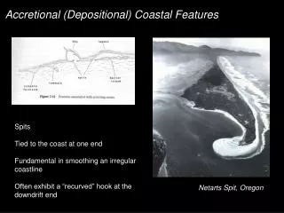
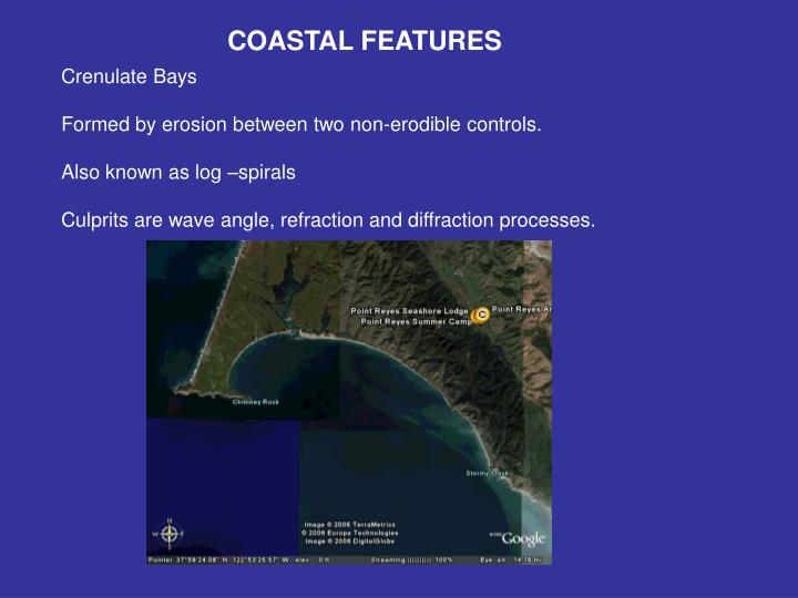
COASTAL FEATURES. Crenulate Bays Formed by erosion between two non-erodible controls. Also known as log –spirals Culprits are wave angle, refraction and diffraction processes. CRENULATE BAY. One of the best known is Half Moon Bay in California. CRENULATE BAY.

E N D
COASTAL FEATURES Crenulate Bays Formed by erosion between two non-erodible controls. Also known as log –spirals Culprits are wave angle, refraction and diffraction processes.
CRENULATE BAY One of the best known is Half Moon Bay in California
CRENULATE BAY Can fit with log spiral of the form (Yasso, 1965) D&D Where r is distance form center θ is angular coord θ0 is reference value for r=r0 α controls rate at which radius increases.
CRENULATE BAY Effect of varying alpha
CRENULATE BAY Effect of varying r0, like varying wave angle I love matlab!
CRENULATE BAY Can become a particularly bad problem when the sediment supply versus carrying capacity is small. Examples: throat of inlet. St George Inlet, FL Gray’s Harbor, WA cirp.chl.wes.army.mil
CUSPS Rhythmic features in the alongshore direction located on the foreshore. No agreement as to formation mechanism and maintenance Typical conditions: Steep foreshore Surging waves Shore normal waves Narrow wave spectrum Medium sand and up Looks like a crenulate bay
CUSPS Flow within them Kuenan (1948) observed alternating surges into and out of adjacent embayments LAND Bay Bay Bay Horn Horn Edge wave anti-node Edge wave node
CUSPS Flow within them Bagnold (1940) breaking bore flow piles onto horns and diverges forming to streams that pour into the embayment. Streams from adjacent horns merge and form offshore jet. Dean and Maurmeyer, 1980 Komar, (Bagnold, 1940)
CUSPS Formation Mechanisms (as compiled by D&D)
CUSPS Edge wave Trapped along the coast by refraction, for standing, get fixed alongshore periodicity Ledge Lcusp n is the mode number or number of zero crossing of the cross-shore profile So many modes, can usually find one that matches field spacing
CUSPS Edge wave Higher mode numbers damped by friction, subharmonic period most likely relevant Implying Tedge = 2Twave (Guza and Inman, 1975) Cusp spacing is one half the edge wave wave length. Suggests same flow pattern as observed by Kuenan, 1948, see next slide
CUSPS Edge wave: alternate filling of embayments Time t Time t+Tedge/2
CUSPS Self Organization Numerical model for cusp generation based on simple laws for particle motion and sediment transport Begins with planar beach with small random perturbations Surprisingly not susceptible to changes in model coefficients Get the same current pattern as Bagnold observed.
CUSPS Swash Processes Probably similar to self-organization. Cusp topography and swash tend to cause circulation cells that construct and accentuate cusps Requires wave period approximately equal to natural swash period assuming ballistic motion on a frictionless plane Where Vo is the initial swash velocity Cusp spacing from their model is proportional to the swash magnitude as Where ε defines the relief of the cusp feature and ξ is the maximum excursion length.