Download
1 / 15
150 likes | 225 Views
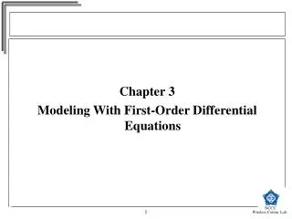
A First Pass at Modeling Horn 3. L. Bartoszek Bartoszek Engineering 12/10/04. Need z dimension for placement of striplines through support module. Elevation view of horn 3 with 183 cm tall man for scale. Isometric view looking downstream.

E N D
A First Pass at ModelingHorn 3 L. Bartoszek Bartoszek Engineering 12/10/04
Need z dimension for placement of striplines through support module Elevation view of horn 3 with 183 cm tall man for scale
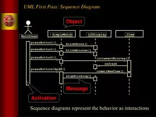
Need this dimension too to fix the ear and stripline design View looking downstream along axis of horn
Close-up of upstream end of horn 3 52 M16 ceramic washer assemblies 128 M10 bolts I did not put in all the bolts holding the ears to the horn yet
Concern about previous picture • That is the largest ceramic ring I’ve ever seen. • I recommend making a part drawing for it and sending it out to Japanese and US ceramics vendors for their comments. • Handling this ring will require some special tooling to avoid cracking from bending stress.
Concern about previous picture • The standard 110° “vee” spray nozzles may be too diffuse to get good heat transfer at the small radius of the center of the horn (“neck”). • May need sharper, more circular nozzles to direct spray at the neck of the inner conductor.
Conclusions • Need more dimensions to finalize the stripline and ear designs • This horn is the original geometry Ichikawa sent me, not reduced by 90 mm (to be able to make flanges from available stock). • Large flanges may be made by forged rings • I am slightly concerned about the relatively thin wall of the outer conductor leading to large tolerances/deflections from circularity • Flanges add stiffness and may keep OC round—only analysis will tell.