Download
1 / 51
510 likes | 517 Views
Chapter-3 Noise Issues. IC Mask Design. Chapter Preview. ■ Worst kind of circuits for noise problems ■ Causes of zaps, spikes, and krrrr sounds ■ Key analogy to remind you of common sense solutions ■ Why you might suggest a certain library ■ How to create a Wall of Death

E N D
Chapter-3Noise Issues IC Mask Design
Chapter Preview • ■ Worst kind of circuits for noise problems • ■ Causes of zaps, spikes, and krrrr sounds • ■ Key analogy to remind you of common sense solutions • ■ Why you might suggest a certain library • ■ How to create a Wall of Death • ■ Or two Walls of Death, one for you • ■ Timing solution • ■ Location, location, location • ■ How to make a 360° shield • ■ Running two lines instead of one • ■ Placing a capacitor in the neighborhood • ■ Stacking your power rails • ■ Unwanted secret signals created by your main signals
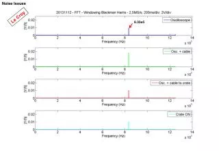
Opening Thoughts on Noise Issues • Noise: • Unwanted signal in circuits; • It is a big problem,especially when picking up a weak signal locatednext a noisy circuitry; • In mixed signal circuit, noise can ruin a chip; • It’s crucial that the mask designer know as much about cutting down the noise as possible.
Shielding the noisy circuit • Two ways to reduce noise • in the design world • in the layout world • Noise circuit Moves Inside Their House
Shielding the noisy circuit • wrap a big ring of ground substrate contacts around the whole block. • When the noise tries to escape the block through the substrate, it encounters a ground substrate contact. its voltages or noise currents will be attracted to this contact since it is grounded.
Shielding the noisy circuit- contact • Substrate contact should be many more as possible Reduce the resistance
Shielding the quiet block • Both block are needed to blocking
Making far away • Making the noisy block and quiet block far away
Wire Solutions • Coaxial Shielding.
Decoupled Power Rails Adding capacitance and inductance
Stacked Power Rails Providing decoupling capacitors by using the parasitic capacitance between the power and ground
Floorplanning • No fixed floorplane • The floorplane depends on the function and other objectives of your particular chip • Better for this one, maybe worse for another one
ESD Supply Strategies • Suppose four pins per side, and pins 1, 5, 7, and 9 are protected to VCC 1 and GND 1. • Suppose pins 6, 8, 10, and 14 are protected to VCC2 and GND2. • all the other pins have signals that are protected to VCC 3 and GND3
Floorplane when considering ESD • Left figure is difficult to wire the ESD power supply; • Right figure is easier to wire the ESD power supply;
Block-Driven Planning • Better planning can reducing the wires crossing
Floorplan from inside to outside • Rearranged blocks now align with our premiere pin-out plan
Signal-Driven Planning • 根据信号流程来安排内部模块; • 根据内部电路的对称要求来布局(高频电路);
Reshaping Blocks • 高频时,将输入管放在Pad之间,这时可缩短输入路径,尽可能地提高电路的工作频率
芯片尺寸估计 间距太小 • 留出更多的空间以便更易布通走线
用过去经验来估计尺寸 • 借鉴以前已经成功流片,通过对其内部电路模块的分析来确定所需面积的大小。 • 可以利用预先知道的走线关系来辅助确定内部局部芯片布局; 已知内部走线关系
回顾总结 • 布局可以加速版图设计,提高电路成功概率 • ■ 由I/O来决定布局 • ■ 由块(block)结构来决定布局 • ■ 由信号来影响布局 • ■ 反复调整布局的过程 • ■ 调整块结构 • ■ 从连线, 速度, 和其它一些因素来考虑 • ■ 借助以前成功芯片的布局经验 • ■ 芯片尺寸估计技巧 • ■ 布局常犯的错误 • ■ 常遇到的问题和解决方法
Layout的一些技巧 • 1. 记住一些最常用的5-6条设计规则; • 最小尺寸非强制尺寸,它们仅仅是最低标准;(模拟电路) • 例:Metal1:0.6u, Metal2:0.7u, and 0.8 for Metal3; 布线可以以1u为准
只记5-6条规则的优点 • 由于不用记住太多的规则,所以可以很快地上手绘制版图。 • 可以使的电路的性能有所提升。 • 在版图上留有一定的余量,可以为后续调整提供空间 。
设计技巧 • 高频信号线走在寄生效应最低的金属层上;在该层为高频信号留下走线通道; • 走线在一定范围内尽可能宽以降低寄生电阻
Directional Layer Technique • Metal One horizontally and running all Metal Two vertically? Ingenious.
Change directions • Do you think we still use Metal Two for our vertical run if we are only moving, say, one or two grids? If the vertical jump is only one or two grids, you generally stay in the same metal.
Rule of Thumb: Don’t bother changing metals for short jumps. • The vias we introduce for such a small run can potentially introduce high resistances. • Not only that, but vias can sometimes not etch properly. So, for small jumps of only one or two grids, it is not as reasonable to use your second layer of metal. Stay in Metal One.
Library Rules for Grid-Based Systems • Devise a set of rules for everything dealing with our layout, when we use a grid-based router. • Typically, we construct an entire standard cell library according to these rules. Every cell, every inverter, every NAND gate, absolutely everything conforms to the rules.
Input and Output Alignment • Schematic reference for our standard inverter cell. We need input A and output Z to align perfectly with our grid wires, or they will miss the connections placed by the auto-router. • the input and output, A and Z, located in the center of the cell. • They must be located exactly on the same grid as all the wiring. How else would our wiring attach?
Grid-based Inverter • All standard cell components have to be matched to the grid in this same way. • The wires, the cells, the intersections—all layout entities need to obey the rules, such as alignment and isolation distances. Otherwise, we cannot guarantee that our automated system will give us a DRC and LVS clean job.
Fixed Height, Variable Width Difficult to route power and ground
Digital libraries: fixed height, variable width. • How to deal with large loads • If we need bigger logic gates with larger transistors to drive large loads, then we just make the cell wider and split the transistors to fit inside the rails. But, we still maintain the fixed library height. • Height decision: • Typically, select a height that is a bit larger than the minimum, because you want to have a power rail that is larger than minimum. • Fixed height, variable width is also a very useful technique to use in analog design. • If you have a very repetitive design, with lots of similarly sized cells
Determining Wire Gauge • Our 1-grid wire sets the minimum distance between grid lines, as we saw earlier. • One wire runs along one grid line. We can also make wires of larger gauges. The power rail in our inverter example is what we call a 3-grid wire. Typically, power rails are either 2- or 3-grid wire. • To build a 3-grid wire, place three single grid wires on-grid, running side by side, and then fill the gaps between them with metal.
Common N Well • Suppose we want to place four gates next door to each other. Typically, we want to place them as close as possible. • The above design method wastes large amounts of space. Luckily, because most logic circuits have the PMOS devices connected to VDD along with the N well, we can create one large single N well and save space.
Common N Well • one large N well now means that our limiting design rule is the transistor-to-transistor rule, which is much smaller. We can place our devices closer together by sharing the N well.
Common N Well • The N well and the power rails butt against each other forming long, continuous N well and power rail strips.
Half-Grid Cell Sizing • keep all internal wiring on-grid. The ends of the cells that butt against each other falling between gridlines, on the half-grid. • so every edge of a cell—top, bottom, left, and right—needs to end on a half-grid. That keeps our internal components properly spaced on all sides.
Half Design Rule • Placing components one half minimum design rule distance from each edge puts one full design rule distance between components.
Power & Ground Connection Typical power ring using Metal Two buses
Routing Channel • Leave room at the extent for additional wiring. • This arrangement requires no flipping of rows, and allows room to wire in lower metals.
Routing Channel The routing channels, by the way, can be any height we want. We can make cells any dimensions to fit our needs.
Channel Routers • Channel routers create channels between cells. • Architecture: A whole bunch of cell rows, then a big gap, then more cell rows. • Channel routers build in channels for wiring between rows of cells. • A channel-based approach leaves room for wires to be placed along designated channels. • Two architecture: • Fixed channel width • Variable channel width
Fixed Channel width • The wires and their gaps are evenly spaced. • Simpler to automate routing, but could be wasteful. Every channel does not necessarily need the same gap for wiring.
Variable Channel width • Varying channel width according to need; • Characteristic: • can give a much more compact die, a much smaller chip. • But, the software that drives the placement of cells has to be much more sophisticated, able to handle much more information. It announces higher demand to the Routing Tool;
Antenna Rule • is a design rule check that makes sure that any CMOS gate is tied to a diffusion before Metal One is processed. • add a small reverse biased protection diode. • Guarantee that any input will be tied down, • Usage: protected. Place these small protection diodes usually on the inputs to an FET gate. • internal FET gates do not need any NAC • The output of a device can provide protection for the gate it is driving. • For instance: The internal FET gates of a big flip-flop are usually protected automatically by this connection. But for the inputs of an inverter, for instance, you have to build these protection diodes into your cells up front.
NAC diodes • Have to build NAC diodes into all logic gates, particularly the inputs of standard cells. • Cause: cannot guarantee standard cell will be driven directly from a diffusion in Metal One. • For instance: an input gate could be accessed in Metal Two.