1 / 0

Thermal Noise and Material Related Issues

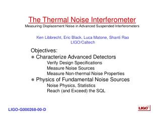
Thermal Noise and Material Related Issues. Ronny Nawrodt 1 , Iain Martin 2 23/08/2011 1 Friedrich-Schiller-Universität Jena, Germany 2 SUPA University of Glasgow, Scotland. Overview. thermal noise in GW detectors (revision) important material properties mechanical loss measurements bulk

raine
Download Presentation

Thermal Noise and Material Related Issues

An Image/Link below is provided (as is) to download presentation Download Policy: Content on the Website is provided to you AS IS for your information and personal use and may not be sold / licensed / shared on other websites without getting consent from its author. Content is provided to you AS IS for your information and personal use only. Download presentation by click this link. While downloading, if for some reason you are not able to download a presentation, the publisher may have deleted the file from their server. During download, if you can't get a presentation, the file might be deleted by the publisher.

E N D

Presentation Transcript


  1. Thermal Noise and Material Related Issues

    Ronny Nawrodt1, Iain Martin2 23/08/2011 1Friedrich-Schiller-Universität Jena, Germany 2SUPA University of Glasgow, Scotland
  2. Overview thermal noise in GW detectors (revision) important material properties mechanical loss measurements bulk coatings (optics…) summary
  3. Thermal noise in GW detectors
  4. Thermal noise in GW detectors GW detectors are amongst the most sensitive tools today. operation at the technical and scientifical limitations (noise, cross coupling, etc.) improving the instruments means fighting with physics novel techniques (setups, cryogenics, etc.) novel materials (change of material for optical components) …
  5. Thermal noise in GW detectors The first generation of interferometric GW detectors (LIGO, Virgo, GEO600, TAMA300) reached their design sensitivities in a wide range of frequencies.
  6. Thermal noise in GW detectors current detectors are based on: fused silica optics (best optical material currently available) fused silica or metal suspensions friction between the suspension and the optics can be avoided by using the low mechanical loss jointing technique of hydroxide catalysis bonding
  7. Thermal noise in GW detectors Currently, the second generation of GW detectors is being built based on the experiences of the first generation of GW detectors and novel techniques that have been tested. further improvements: aLIGO, aVirgo, GEO-HF fused silica, room temperatur, monolithic suspensions (demonstrated in GEO600 for years) LCGT + CLIO sapphire, cryogenics pioneering work in the field of cryogenic large scale interferometry
  8. Thermal noise in GW detectors As thesecondgenerationisdesignedandcurrentlyabouttobeingbuiltresearchersstarted a conceptual design studyfor a 3rdgenerationdetector– the Einstein Telescope design study. aims: Whattechnologiesareneededtoincreasesensitivityby a factorof 10 comparedto 2nd generation? Howmight such a design looklike? Whichmaterialsshouldbeused? Which design? (Howmuchdoesitcost?) homepage: www.et-gw.eu
  9. Thermal noise in GW detectors artist view of ET – check www.et-gw.eu for details
  10. Thermal Noise in GW detectors improvement of the sensitivity between different generations of GW detectors:
  11. Thermal noise in GW detectors Parts of the Einstein Telescope have to be operated at cryogenic temperatures to reduce thermal noise. natural links between ET and LCGT: cryogenics pulse tube vs. LHe cooling contamination of the mirrors due to cryotrapping general: pioneering technology in cryogenics people exchange between Japanese and Einstein Telescope researchers now extended through personal exchange program
  12. Thermal noise in GW detectors a reminderofthermal noise: two different types (1) fluctuating thermal energy Brownian thermal noise (2) fluctuatingtemperature  thermo-elastic, thermo- refractive, thermo-optic temperaturedependentparameter (e.g. CTE, dn/dT) links temperaturefluctuationandphasefluctuationofthedetector
  13. Thermal noise in GW detectors a reminder of bulk thermal noise main message: material properties influence strongly the thermal noise – (nearly) all of them are temperature dependent =0 possible for some materials, e.g. silicon (@ 18 and 125 K) Thermo-elastic noise: Brownian thermal noise: beam diameter temperature
  14. Thermal noise in GW detectors a reminder of bulk thermal noise similar with thermo-optical noise and finite corrections Thermo-elastic noise: Brownian thermal noise: beam diameter temperature
  15. Material properties
  16. Overview of material properties mechanicalproperties basicproperty: strengthofthe material (especiallyforsuspensionelements) [IGR Glasgow]
  17. Overview of material properties mechanicalproperties Young‘smodulus, Poissonratio massdensityofthe material availablesize (growingmethods) optimumcrystalorientation mechanicallosstodetermineBrownian thermal noise (= mainfocusofthislecture) [Wacker]
  18. Overview of material properties thermal properties stronglytemperaturedependent crystallinematerialsfollow „basic“ thermodynamics / statistics (Debye theory) heatcapacity (~ T3atlowtemperaturesforcrystals) thermal conductivity (removalofheat!) coefficientof thermal expansion
  19. Overview of material properties thermal properties thermal conductivity increasing impurity concentration (scattering of phonons on impurities) + size effects (boundary scattering) log scale  not enough phonons left to carry heat [Touloukian] log scale 
  20. Overview of material properties thermal properties coeffcientof thermal expansion larger CTE forcryst. materialscomparetoamorphous (reason: summationoftinyeffects in thecrystal) usually CTE decreaseswithdecreasingtemperature somematerialsshowtemperatureswith CTE = 0 (e.g. silicon @ 18 and 125 K)
  21. Overview of material properties opticalproperties refractiveindex n forming HR mirrorcoatings thermo-refractivecoefficientdn/dT determinesthe thermo-refractivenoise opticalabsorption sets a fundamental limittotheminimum operational temperature
  22. Mechanicalloss - Introduction -
  23. Basics of mechanical loss elasticbehaviourof a solid Hook‘s Law … stress … strain E … Young‘smodulus (German: modulusofelasticity) instantaneous reaction, full recovery
  24. Basics of mechanical loss anelasticbehaviourof a solid anelasticity relaxation only partial instantaneousreaction, fullrecovery after t = 
  25. Basics of mechanical loss periodic process – anelasticity and mechanical loss hysteresis (= energy loss) work done by the system work done on the system
  26. Basics of mechanical loss isothermal adiabatic energy dissipation per cycle frequency f
  27. Basics of mechanical loss definitionofthemechanicalloss = phase lag between stress andstrain measurement via themechanical Q-factorat a resonance keep in mind: The mechanicallossis a continuousfunction of frequency but we just probe itatcertainfrequencies (resonant frequencies) of a system nofullknowledgeavailable.
  28. Loss mechanisms Therearemany different originsofloss in solids. Focus on 3 dominant ones: phonon-phonon interaction thermo-elasticloss impuritydrivenlosses Phonon-phonon-damping (Akhiezer-/Landau-Rumer-Damping) Phonons areforming a certaindistributionwhen in equilibrium. Atlowfrequencyexcitationstheacousticvibration (= phonon) modulatesthelattice newlocal equilibrium  redistributionconsumesenergy  loss.
  29. Loss mechanisms Phonon-phonon-damping (Akhiezer-/Landau-Rumer-Damping) Phonons areforming a certaindistributionwhen in equilibrium. Atlowfrequencyexcitationstheacousticvibration (= phonon) modulatesthelattice newlocal equilibrium  redistributionconsumesenergy  loss. (Akhiezerloss) Ifthephononenergyis high (high frequencyvibration) theacousticphonondirectlyinteractswiththephononsofthegivendistribution  directphononscattering  redistributionconsumesenergy  loss. (Landau-Rumer-Loss)
  30. Basics of mechanical loss thermo-elasticdamping If a sample isdeformedcertainparts will becompressedor expanded localheatingorcooling (depending on CTE). Sample isnow in thermal non-equilibrium  heatflux  entropyisincreased  loss. impuritydrivendamping Impuritiescanoccupy different positions in a lattice depending on theapplied stress. If an externalvibration isapplieditmightbeenergeticbettertochangepositions  loss.
  31. EA energy position Basics of mechanical loss The transition between 2 (quasi-)stable positions can be modelled with a double-well potential: „Debye peak“  … relaxation strength  … relaxation time 0 thermally activated process: =0 EA … activation energy 0 … relaxation constant
  32. f0 amplitude amplitude Df time frequency Basics of mechanical loss ring-down measurements bandwidth measurements
  33. + + - Basics of mechanical loss excitationofmodes mechanical (e.g. piezo) electro-static vibrationread-out electricalread-out (capacitor) opticalread-out (e.g. opticallever, interferometrictechniques)
  34. Mechanicalloss - Bulk Materials -
  35. Selected examples - Quartz crystalline quartz is well known  toy material to investigate setups and data processing tools silicon hydrothermal growth of crystal grownfromsolutionunderpressure (~ 500 bar) atelevatedtemperatures containing: water silicondioxide sodiumcarbonate / hydroxide oxygen cryst. quartz shows channels along its c-axis
  36. Selected examples - Quartz loss peaks associated with sodium impurities trapped in multiple well potential along the c-axis Si O lossprocessisorientationdependent detailedstudyneeds different cryst. cutsfromthe same material activation energy from experiment: ~ 55 meV
  37. Selected examples – Fused Silica fusedsilica: verylowlossatroomtemperaturereaching 410-10 large losspeakaround 30K not suited for cryogenic use in GW detectors origin of the peak: Amorphous silica has a near but no far order. Thus, loss processes get a distribution of loss parameters. The peak is the superposition of all of them.
  38. Selected examples – Sapphire/Silicon crystallinematerialsneededforcryogenicoperation different candidatematerialshavebeendiscussed in thepast possiblecandidatematerialsaresapphire (LCGT) and Si (ET) reasons: bothareopticalmaterials (remember, FS iscurrentlythebestoptical material) bothareavailable in rather large pieces high thermal conductivity coatingtechniquesavailable whilesapphirecanbeoperatedat 1064nm silicondemands a changeofthelaserwavelength due toitsopticalabsorption
  39. Selected examples – Sapphire/Silicon mechanical loss of silicon and sapphire is comparable at cryogenic temperatures (Q‘s up to several 109 achieved) test measurement of silicon and sapphire samples [U Jena]
  40. Selected examples – Sapphire/Silicon detailed investigation of intrinsic loss mechanisms in promising candidate bulk materials ongoing questions: general loss processes? impurities? tolerable level of impurities? heat treatment to remove dislocations? surface loss? … collaboration of several groups (Jena, Glasgow, Legnaro, starting collaboration with Japan) to investigate intrinsic damping of materials (coatings, bulk, surfaces, etc.)
  41. Mechanical loss - Coating Materials -
  42. Optical coatings Requirements – high reflectivity, low optical absorption (< 1ppm) Multilayer coatings of dielectric materials, l/4 thick Reflectivity from difference inrefractive index, and numberof layers, 2N. Current detectors use silica (n=1.45) / tantala (n=2.03) coatings,~ 15 bi-layers
  43. Coating thermal noise Levin – interferometer most sensitive to mechanical loss close to the reflected laser beam Thus mechanical loss of coatings is particularly important Coating loss dominated by the loss of the tantala layers ftantala~ 410-4 fsilica~ 510-5 Measurements suggested no observable loss from coating layer interfaces (however recent results from LMA, Lyon, suggest some interface loss may be observable) Doping Ta2O5 with TiO2 can reduce the loss by ~40%.
  44. Coating thermal noise Coating thermal noise expected to limit achievable sensitivity of future GW detectors at their most sensitive frequencies Coating thermal noise
  45. Coating loss measurements First cryogenic measurement of silica/tantala coating by Yamamoto et al, showed possible slight increase in loss at low temperature Cryogenic loss studies of mono-layers of individual coating materials carried out in collaboration between Glasgow, Jena, LMA Study individual materials in isolation Identify microscopic dissipation mechanisms Test coating performance at cryogenic temperatures Single layer coatings of silica (left) and tantala (right), clamped for loss measurements
  46. Measuring coating loss - 1 34mm electrostatic drive 50mm thick Coating applied here 500mm tantala coating loss from free decay of amplitude Single layers of a coating material applied to silicon cantilever substrates Loss measured from exponential ring-down of bending modes coated cantilever in clamp within cryostat bending modes excited via eletrostatic drive
  47. Measuring coating loss - 2 Loss of coating layer calculated from difference in loss of a coated and un-coated cantilever Scaling factor accounts for fraction of total elastic energy stored in the coating (c) (b) (a) Loss of (a) uncoated silicon cantilever with thermal oxide layer, (b) cantilever coated with 500 nm of TiO2-doped Ta2O5 (14.5% Ti) and (c) the calculated loss of the coating layer
  48. Loss peak analysis - tantala Debye-like mechanical loss peaks thermally activated process  … relaxation strength  … relaxation time EA … activation energy 0 … relaxation constant double well potential without external stresses
  49. Loss mechanism parameters – Arrhenius plot Activation energy (40 ± 3) meV for TiO2 doped Ta2O5 (29 ± 2) meV for undoped Ta2O5 Doping with TiO2 increases the activation energy. Transition between two stable states appears to be hindered
  50. Possible microscopic processes no long-distance order in coating materials (amorphous) possible transitions of atoms / atom groups doping might block possible positions  increase of activation energy O O Ta Ta Ta Ta O Ti
  51. Distribution of model parameters Debye loss peak plotted using calculated activation energy and relaxation constant Much narrower than experimental peak Amorphous structure results in a distribution of activation energies.
  52. Distribution of parameters refined model: asymmetric double-well potential barrier height distribution g(V) asymmetry distribution f(D) [Gilroy, Phillips 1981] g represents the coupling between strain and the dissipation mechanism Ciiis the elastic constant of the material
  53. Distribution of barrier heights asymmetric double well potential: barrier height distribution contains information about the microscopic structure doping changes height and distribution of barrier heights g(V)f0 [Gilroy, Phillips 1981] g(V) … barrier height distribution [Martin et al. 2009]
  54. Effect of heat treatment temperature on Ta2O5 loss Three loss peaks, triggered at different post-deposition heat-treatment temperatures 800 C 800 C 800 C 800 C 800 C 800 C 800 C 800 C 800 C 600 C 600 C 600 C 600 C 600 C 600 C 600 C 400C 400C 400C 400C 300C 300C (i) Loss at 1.9 kHz of 0.5 mm thick un-doped Ta2O5 coatings heat treated at 300,400, 600 and 800 C. (Coatings from CSIRO)
  55. 35 K peak Observed in Ta2O5 heat treated at 300, 400 C, and likely in Ta2O5 heat treated at 600 C Activation energy 54 meV Analogous to dissipation peak in fused silica, involving thermally activated transitions of oxygen atoms? Effect of heat treatment temperature on Ta2O5 loss 300 C 800 C 600 C 400C 300C 800 C 800 C 800 C 800 C 800 C 800 C 800 C 800 C 800 C (i) 600 C 600 C 600 C 600 C 600 C 600 C 600 C Above: Electron diffraction pattern of Ta2O5 heat treated at 600 C Left: Loss at 1.9 kHz of 0.5 mm Ta2O5 coatings annealed at 300,400, 600 and 800 C. 400C 400C 400C 400C 300C 300C
  56. Effect of heat treatment temperature on Ta2O5 loss 18 K peak Observed in Ta2O5 heat treated at 600 C and 800 C Related to structural changes brought on by heat treatment close to crystallisation temperature? 800 C 600 C 400C 300C 600 C 800 C 800 C 800 C 800 C 800 C 800 C 800 C 800 C 800 C (i) 600 C 600 C 600 C 600 C 600 C 600 C 600 C Above: Electron diffraction pattern of Ta2O5 heat treated at 600 C Left: Loss at 1.9 kHz of 0.5 mm Ta2O5 coatings annealed at 300,400, 600 and 800 C. 400C 400C 400C 400C 300C 300C
  57. Effect of heat treatment temperature on Ta2O5 loss 90 K peak Observed in coating heat treated at 800 C Large, broad loss peak likely to be related to (expected) onset of polycrystalline structure due to high temperature heat treatment. Loss mechanism could be e.g. phonon scattering at grain boundaries 800 C 800 C 600 C 400C 300C 800 C 800 C 800 C 800 C 800 C 800 C 800 C 800 C 800 C 800 C (i) 600 C 600 C 600 C 600 C 600 C 600 C 600 C Above: Electron diffraction pattern of Ta2O5 heat treated at 800 C Left: Loss at 1.9 kHz of 0.5 mm Ta2O5 coatings annealed at 300,400, 600 and 800 C. 400C 400C 400C 400C 300C 300C
  58. Loss of silica coatings Scatter at higher temperatures, possibly due to loss into clamp. Repeated room temperature measurement of silica coating loss. Loss of SiO2 will have a significant contribution to coating thermal noise below 100 K
  59. Coating thermal noise at 100 Hz If coating loss was constant with temperature, could gain factor of ~ 4 in TN at 18 K Measured coating losses imply we can only gain a factor of ~ 1.7 in coating TN by cooling to 18 K Using measuredcoating loss Using measuredcoating loss Optimistic estimate – coating loss remains constant at all T Optimistic estimate – coating loss remains constant at all T
  60. Probing links between atomic structure and loss Short range structure of amorphous materials probed by Reduced Density Function analysis of TEM electron diffraction data RDF is a Fourier transform of the information gained from the intensity profile of a diffraction pattern RDF gives statistical representation of where atoms are located with respect to a central atom
  61. The Reduced Density Function (RDF) Ta O distance Ta Ta distance G(r) G(r) G(r) G(r) r (Å) RDFs of heat-treated tantala coatings1 Interpreting RDFs Peak position - nearest neighbour distances Peak height – nearest neighbour abundances Peak width – indicates level of order in structure
  62. Structural modelling Distribution Bond angle (degrees) RDF can be used as basis for Reverse Monte Carlo models of the microstructure, allowing e.g. bond angle distributions to be extracted Molecular dynamics simulations used to ensure models are energetically stable Ta – blue O - red
  63. Current / future coatings research Alternative high-index coating materials e.g. amorphous Si, hafnia Alternative low-index materials e.g. Al2O3 Exploring links between short-range atomic structure and loss Reduced coating / coating-free optics – diffractive optics and resonant waveguide mirrors
  64. Optical Properties
  65. Important Properties refractive index n  influences coating selection thermo-refractive coefficient dn/dT  governs the thermo-refractive noise optical absorption   limits the operation at low temperatures and at high laser powers all these parameters are needed at low temperatures!
  66. Research on the refractive index of Si at low temperatures classical prism experiment needed to determine refractive index method of minimum deviation with high resolution cryogenic actuators method of minimum deviation in Littrow-order experimental setup for cryogenic measurements of the refractive index A – laser, B – beam splitter, C – Faraday isolator, D – cryostat, E- prism, F- detector
  67. Research on the thermo-refractive coefficient of Si incoming light outcoming light internal reflections Fabry-Perot-Cavity filled with silicon, dn/dT determines optical path length inside FPC
  68. Research on the optical absorption of silicon at low T. k simplified electronic band structure CB VB indirect transition direct transition phonon contribution photons do not carry momentum Dk = 0 Dk = kphonon Ephoton + Ephonon = E photonswith E < Egap=1.1eV canbe absorbedbyassistanceofphonons
  69. Research on the optical absorption of silicon at low T. phonon 1 phonon photon 2 phonons 3 phonons 300 K densityofphononsisstronglytemperaturedependent muchsmallerabsorptioncanbeexpectedatlowtemperatures [Keeves et al., J. Appl. Phys.]  measurements ongoing
  70. Summary
  71. What have we learned? material properties strongly determine the thermal noise performance of a detector simple temperature scaling is dangerous and leads to wrong results impurities determine mechanical losses  strong influence on thermal noise material science (understanding temperature behaviour of parameters) is needed to optimise future detectors a wide and open field…
More Related