Download
1 / 15
160 likes | 428 Views
Chapter 3: PCM Noise and Companding. Quantization Noise Signal to Noise Ratio PCM Telephone System Nonuniform Quantization Companding. Huseyin Bilgekul Eeng360 Communication Systems I Department of Electrical and Electronic Engineering Eastern Mediterranean University. Quantized Signal

E N D
Chapter 3:PCM Noise and Companding • Quantization Noise • Signal to Noise Ratio • PCM Telephone System • Nonuniform Quantization • Companding Huseyin Bilgekul Eeng360 Communication Systems I Department of Electrical and Electronic Engineering Eastern Mediterranean University
Quantized Signal XQ Signal X Quantization Noise nQ Quantization Noise • The process of quantization can be interpreted as an additive noise process. • The signal to quantization noise ratio (SNR)Q=S/N is given as:
Effects of Noise on PCM • Two main effects produce the noise or distortion in the PCM output: • Quantizing noise that is caused by the M-step quantizer at the PCM transmitter. • Bit errors in the recovered PCM signal, caused by channel noise and improper filtering. • If the input analog signal is band limited and sampled fast enough so that the aliasing noise on the recovered signal is negligible, the ratio of the recovered analog peak signal power to the total average noise power is: • The ratio of the average signal power to the average noise power is • M is the number of quantized levels used in the PCM system. • Pe is the probability of bit error in the recovered binary PCM signal at the receiver DAC before it is converted back into an analog signal.
Effects of Quantizing Noise • If Pe is negligible, there are no bit errors resulting from channel noise and no ISI, the Peak SNR resulting from only quantizing error is: • The Average SNR due to quantizing errors is: • Above equations can be expresses in decibels as, Where, M = 2n α = 4.77 for peak SNR α = 0 for average SNR
DESIGN OF A PCM SIGNAL FOR TELEPHONE SYSTEMS • Assume that an analog audio voice-frequency(VF) telephone signal occupies a band from 300 to 3,400Hz. The signal is to be converted to a PCM signal for transmission over a digital telephone system. The minimum sampling frequency is 2x3.4 = 6.8 ksample/sec. • To be able to use of a low-cost low-pass antialiasing filter, the VF signal is oversampled with a sampling frequency of 8ksamples/sec. • This is the standard adopted by the Unites States telephone industry. • Assume that each sample values is represented by 8 bits; then the bit rate of the binary PCM signal is 8 • This 64-kbit/s signal is called a DS-0 signal (digital signal, type zero). • The minimum absolute bandwidth of the binary PCM signal is This B is for a sinx/x type pulse sampling
DESIGN OF A PCM SIGNAL FOR TELEPHONE SYSTEMS • If we use a rectangular pulse for sampling the first null bandwidth is given by • We require a bandwidth of 64kHz to transmit this digital voice PCM signal, whereas the bandwidth of the original analog voice signal was, at most, 4kHz. • We observe that the peak signal-to-quantizing noise power ratio is: • Note: • Coding with parity bits does NOT affect the quantizing noise, • However coding with parity bits will improve errors caused by channel or ISI, which will be included in Pe ( assumed to be 0).
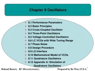
Nonuniform Quantization • Many signals such as speech have a nonuniform distribution. • The amplitude is more likely to be close to zero than to be at higher levels. • Nonuniform quantizers have unequally spaced levels • The spacing can be chosen to optimize the SNR for a particular type of signal. Output sample XQ 6 4 Example: Nonuniform 3 bit quantizer 2 -8 -6 8 -4 -2 2 4 6 Input sample X -2 -4 -6
Companding • Nonuniform quantizers are difficult to make and expensive. • An alternative is to first pass the speech signal through a nonlinearity before quantizing with a uniform quantizer. • The nonlinearity causes the signal amplitude to be Compressed. • The input to the quantizer will have a more uniform distribution. • At the receiver, the signal is Expanded by an inverse to the nonlinearity. • The process of compressing and expanding is called Companding.
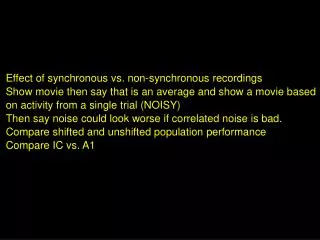
-Law Companding • Telephones in the U.S., Canada and Japan use -law companding: • Where = 255 and |x(t)| < 1 Output |x(t)| Input |x(t)|
y x x’ x’ Q(.) C(.) Uniform Quantizer Compressor Non Uniform quantizing • Voice signals are more likely to have amplitudes near zero than at extreme peaks. • For such signals with non-uniform amplitude distribution quantizing noise will be higher for amplitude values near zero. • A technique to increase amplitudes near zero is called Companding. Effect of non linear quantizing can be can be obtained by first passing the analog signal through a compressor and then through a uniform quantizer.
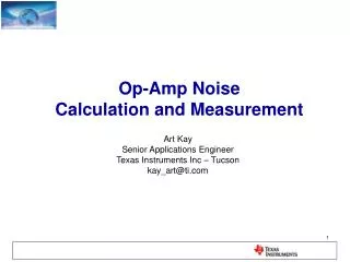
Example: m-law Companding x[n]=speech /song/ y[n]=C(x[n]) Companded Signal Close View of the Signal Segment ofx[n] Segment of y[n] Companded Signal
A-law and m-law Companding • These two are standard companding methods. • u-Law is used in North America and Japan • A-Law is used elsewhere to compress digital telephone signals
SNR of Compander • The output SNR is a function of input signal level for uniform quantizing. • But it is relatively insensitive for input level for a compander
SNR Performance of Compander • The output SNR is a function of input signal level for uniform quantizing. • But it is relatively insensitive for input level for a compander. • α = 4.77 - 20 Log( V/xrms) for Uniform Quantizer • V is the peak signal level and xrms is the rms value • α = 4.77 - 20log[Ln(1 + μ)]for μ-law companding • α = 4.77 - 20 log[1 + Ln A]for A-law companding
V.90 56-Kbps PCM Computer modem • The V.90 PC Modem transmits data at 56kb/s from a PC via an analog signal on a dial-up telephone line. • A μ law compander is used in quantization with a value for μof 255. • The modem clock is synchronized to the 8-ksample/ sec clock of the telephone company. • 7 bits of the 8 bit PCM are used to get a data rate of 56kb/s ( Frequencies below 300Hz are omitted to get rid of the power line noise in harmonics of 60Hz). • SNR of the line should be at least 52dB to operate on 56kbps. • If SNR is below 52dB the modem will fallback to lower speeds ( 33.3 kbps, 28.8kbps or 24kbps).