Download
1 / 38
420 likes | 693 Views
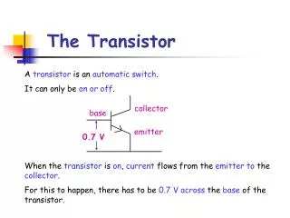
0.7 V. The Transistor. A transistor is an automatic switch . It can only be on or off. collector. base. emitter. When the transistor is on , current flows from the emitter to the collector . For this to happen, there has to be 0.7 V across the base of the transistor.

E N D
0.7 V The Transistor A transistor is an automatic switch. It can only be on or off. collector base emitter When the transistor is on, current flows from the emitter to the collector. For this to happen, there has to be 0.7 V across the base of the transistor.
If the voltage across the base is less than 0.7 V, the transistor is switched off and no current flows.
VS 0 V Automatic Night Light Experiment An automatic night light is constructed as shown.
VVR VS VLDR 0 V • How It Works • In bright light: • resistance of the LDR is low (LURD) • if resistance of LDR is low, this meansvoltage across LDR is also low. • base voltage is low ( < 0.7 V). • transistor is OFF • LED does not light • In dim light: • resistance of LDR increases • voltage across LDR increases • base voltage increases ( > 0.7 V) • transistor switches ON causing LED to light.
This circuit switches on a light when it is dark and switches it off when it is light. Putting the LDR at the top (reversing the components) makes the circuit do the opposite. Devices Input: Process: Output: voltage divider transistor LED
VS Vtherm VVR 0 V Temperature Control Experiment An automatic temperature control circuit is constructed as shown.
Vtherm VS VVR 0 V • How It Works • As the temperature increases: • resistance across thermistor falls (TURD) • this means voltage across thermistor falls • voltage across variable resistor increases • base voltage increases ( > 0.7 V) • transistor switches ON • LED lights. This circuit switches on a light when the temperature increases. Putting the thermistor at the bottom (reversing the components) makes the circuit do the opposite.
Yellow Book Switching Circuits – Page 50 Q36, Q37, Q38, Q39
VS R switch C 0 V Time Delay Circuits A time delay circuit is constructed as shown. The CAPACITOR is the input device responsible for the TIME DELAY.
VS R switch C 0 V • How It Works • Switch Open • the capacitor begins to charge up • voltage across capacitor increases • base voltage takes several seconds to reach 0.7 V • as it does so, transistor switches on • LED lights. • Switch Closed • capacitor discharges
Putting the capacitor at the top (reversing the components) makes the circuit do the opposite. The light would switch off after a time delay. Size of Time Delay increase size of R increases time delay decrease size of R decreases time delay increase size of C increases time delay decrease size of C decreases time delay
Yellow Book Switching Circuits – Page 51 Q40 and Q41
A Z B AND Gate The symbol for an AND gate is: A and B are inputs to the AND gate. Z is the output.
The output is only a high voltage ( 1 ) when BOTH input A AND input B are connected to a high voltage ( 1 ) Experiment An AND gate is connected to a light source as shown. A Z B Results The results are recorded in a truth table. 0 0 0 1 0 0 0 1 0 1 1 1
OR Gate The symbol for an OR gate is: A Z B A and B are inputs to the OR gate. Z is the output.
The output is a high voltage ( 1 ) when input A OR input B are connected to a high voltage ( 1 ) Experiment An OR gate is connected to a light source as shown. A Z B Results The results are recorded in a truth table. 0 0 0 1 0 1 0 1 1 1 1 1
NOT Gate The symbol for a NOT gate is: A Z A is the input to the NOT gate. Z is the output.
The output is a high voltage ( 1 ) when input A is NOT connected to a high voltage ( 1 ) Experiment A NOT gate is connected to a light source as shown. Z A Results The results are recorded in a truth table. 0 1 1 0 The NOT gate is also known as an INVERTOR, as it inverts the input. Changes 0 to 1 or vice versa.
LDR Automatic Night Light Experiment Results bright 1 0 dark 0 1
X LDR Night Light With Master Switch Experiment
Results The results are recorded in a truth table. 0 0 1 0 0 1 1 1 1 0 0 0 1 1 0 0
LDR Night Light With Test Switch Experiment A X Z B
Results The results are recorded in a truth table. 0 0 1 1 0 1 1 1 1 0 0 0 1 1 0 1
Combining Logic Gates Example 1 Complete a truth table for the following combination of logic gates. A X B Z C
Gate 1 (AND) A and B are the inputs. X is the output. Gate 2 (OR) X and C are the inputs. Z is the output. 0 0 0 0 0 1 0 0 0 0 0 1 0 0 0 0 0 1 0 1 0 1 1 0 1 1 0 1 0 1 1 1 0 1 1 1 1 1 1 1
Example 2 The following circuit is a combination of logic gates. A Y Z B 2 1 X 3 C (a) State the name of components 1, 2 and 3. (b) Label your circuit diagram with inputs and outputs. (c) Complete a truth table for the circuit shown. 1 = NOT gate 2 = OR gate 3 = AND gate
Gate 1 (NOT) B is the input. X is the output. Gate 2 (OR) A and X are the inputs. Y is the output. Gate 3 (AND) Y and C are the inputs. Z is the output. 0 0 0 1 1 0 1 0 0 1 1 0 0 1 0 0 0 0 0 0 1 1 1 1 0 1 1 0 0 0 1 0 1 1 1 1 1 1 0 0 1 0 1 1 1 0 1 1
Yellow Book Logic Gates – Page 52 Q43, Q44, Q47, Q48, Q50, Q52
Designing Circuits Temperature Sensor ( Hot - 1 ) Light sensor (Light - 1 ) Switch ( Closed - 1 ) Example 1 Draw a circuit and truth table that will switch on a warning LED when a car engine gets too hot. It should only operate when the ignition switch is closed.
LED Temperature Sensor A Z B open & cold 0 0 0 0 1 0 open & hot closed & cold 1 0 0 closed & hot 1 1 1
HEATING Temperature Sensor Example 2 Draw a circuit and truth table that will switch on a central heating system when it is cold, or switched on manually. A Z B X open & cold 0 0 1 1 0 1 0 0 open & hot closed & cold 1 0 1 1 closed & hot 1 1 0 1
MOTOR Temperature Sensor Light Sensor Q1. Design a circuit that will switch a motor on to open greenhouse windows when it is daylight and gets too hot. Give the corresponding truth table for your circuit. A Z B dark & cold 0 0 0 0 1 0 dark & hot light & cold 1 0 0 1 1 1 light & hot
R output C Clock Pulse Generator The clock pulse generator produces a series of pulses that can be used in timing devices. 1 X Y 0 X is the input to the NOT gate. Y is the output.
R X output Y C • Circuit Operation • initially capacitor is uncharged • capacitor charges • capacitor discharges • process repeats over and over again. X = 0 Y = 1 X = 1 Y = 0 X = 0 Y = 1 • Uses • Such counting circuits are essential in devices such as: • digital watches • computers • timing of traffic lights
Frequency of Pulses The frequency of clock pulses depends on the size of resistor and capacitor. Increasing R or C Decreasing R or C It now takes longer for the capacitor to charge and discharge. It now takes less time for the capacitor to charge and discharge.
Clock Pulse Generator 1 sec Digital Clock A digital clock uses a clock pulse generator that has a period of 1 second. The output from the clock pulse generator is binary. Using a decoder and a 7-segment display, we can convert to decimal form.
1 Binary Counter 2 Decoder 4 8 R Reset The Counter The binary counter has a reset terminal which resets the counter to zero when the input to the reset terminal is high (1). If the counter is connected to a 7-segment display, the counter would reset after the number 9. This is achieved using an AND gate. 5 pulses = 5 sec
Yellow Book Clock Pulse Generators – Page 55 Q59, Q60, Q61, Q62