Download

1 / 27
420 likes | 1.36k Views
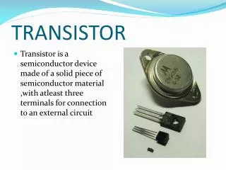
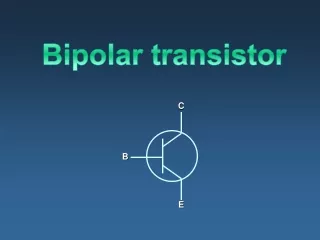
Transistor. BJT Transistors:. NPN Transistor. Sandwiching a P-type layer between two n-type layers. PNP Transistor. Sandwiching a N-type layer between two p-type layers. How a “NPN” Transistor works?.

E N D
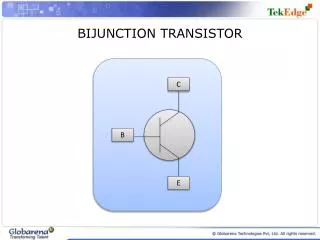
BJT Transistors: NPNTransistor Sandwiching a P-type layer between two n-type layers. PNPTransistor Sandwiching a N-type layer between two p-type layers.
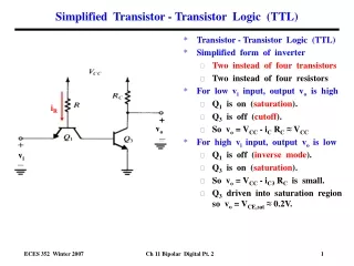
How a “NPN” Transistor works? The base-emitter diode (forward) acts as a switch. when v1>0.7 it lets the electrons flow toward collector. so we can control our output current (Ic) with the input current (Ib) by using transistors. E C B backward Forward
Transistors have three terminals: Collector Base Emitter Active: Always on Ic=BIb Saturation :Ic=Isaturation On as a switch Transistors work in 3 regions Off :Ic=0 Off as a switch
Transistor as a Switch • Transistors can be used as switches.1 Transistor Switch • Transistors can either • conductornot conduct current.2 • ie, transistors can either be onoroff.2
Transistor Switching Example15 X 12V Variable Voltage Supply • When VBE is less than 0.7V the transistor is off • and the lamp does not light. • When VBE is greater than 0.7V the transistor is on • and the lamp lights.
Amplifier example: As you see, the transistor is biased to be always on. The input signal is amplified by this circuit. The frequency of output is the same as its input, but the polarity of the signal is inverted. The measure of amplification is the gain of transistor. Example: Input Amplitude =0.2v Output amplitude=10v Gain=10/0.2=50
Field Effect Transistors JFET MOSFET CMOS
How a JFET transistor works? When the gate is negative ,it repels the electron in the N-channel. So there is no way for electrons to flow from source to drain. When the negative voltage is removed from Gate ,the electrons can flow freely from source to drain .so the transistor is on.
How a MOSFET Transistor works? In MosFET, the Gate is insulated from p-channel or n-channel. This prevents gate current from flowing, reducing power usage. When the Gate is positive voltage ,it allows electrons to flow from drain to source .In this case transistor is on.
How a CMOS transistor works? N-channel & P-channel MOSFETs can be combined in pairs with a common gate . When Gate (input) is high ,electrons can flow in N-channel easily . So output becomes low. (opposite of input) When Gate (input) is low ,holes can flow in P-channel easily. So output becomes high. (opposite of input)
Operational Amplifier (OP AMP) • Basic and most common circuit building device. Ideally, • No current can enter terminals V+ or V-. Called infinite input impedance. • Vout=A(V+ - V-) with A →∞ • In a circuit V+ is forced equal to V-. This is the virtual ground property • An opamp needs two voltages to power it Vcc and -Vee. These are called the rails. A Vo = (A V -A V ) = A (V - V ) + - + -
INPUT IMPEDANCE Input Circuit Output WHY? For an instrument the ZIN should be very high (ideally infinity) so it does not divert any current from the input to itself even if the input has very high resistance. e.g. an opamp taking input from a microelectrode. Impedance between input terminals = input impedance
Impedance between output terminals = output impedance Input Circuit Output OUTPUTIMPEDANCE WHY? For an instrument the ZOUT should be very low (ideally zero) so it can supply output even to very low resistive loads and not expend most of it on itself. e.g. a power opamp driving a motor
Vcc VREF -Vee VIN OPAMP: COMPARATOR Vout=A(Vin – Vref) If Vin>Vref, Vout = +∞ but practically hits +ve power supply = Vcc If Vin<Vref, Vout = -∞ but practically hits –ve power supply = -Vee A (gain) very high Application: detection of QRS complex in ECG
OPAMP: ANALYSIS • The key to op amp analysis is simple • No current can enter op amp input terminals. • => Because of infinite input impedance • The +ve and –ve (non-inverting and inverting) inputs are forced to be at the same potential. • => Because of infinite open loop gain • These property is called “virtual ground” • Use the ideal op amp property in all your analyses
OPAMP: VOLTAGE FOLLOWER V+ = VIN. By virtual ground, V- = V+ Thus Vout = V- = V+ = VIN !!!! So what’s the point ? The point is, due to the infinite input impedance of an op amp, no current at all can be drawn from the circuit before VIN. Thus this part is effectively isolated. Very useful for interfacing to high impedance sensors such as microelectrode, microphone…
OPAMP: INVERTING AMPLIFIER • V- = V+ • As V+ = 0, V- = 0 • As no current can enter V- and from Kirchoff’s Ist law, I1=I2. 4. I1 = (VIN - V-)/R1 = VIN/R1 5. I2 = (0 - VOUT)/R2 = -VOUT/R2 => VOUT = -I2R2 6. From 3 and 6, VOUT = -I2R2 = -I1R2 = -VINR2/R1 7. Therefore VOUT = (-R2/R1)VIN
OPAMP: NON – INVERTING AMPLIFIER • V- = V+ • As V+ = VIN, V- = VIN • As no current can enter V- and from Kirchoff’s Ist law, I1=I2. 4. I1 = VIN/R1 5. I2 = (VOUT - VIN)/R2 => VOUT = VIN + I2R2 6. VOUT = I1R1 + I2R2 = (R1+R2)I1 = (R1+R2)VIN/R1 7. Therefore VOUT = (1 + R2/R1)VIN
SUMMING AMPLIFIER Recall inverting amplifier and If = I1 + I2 + … + In If VOUT = -Rf (V1/R1 + V2/R2 + … + Vn/Rn) Summing amplifier is a good example of analog circuits serving as analog computing amplifiers (analog computers)! Note: analog circuits can add, subtract, multiply/divide (using logarithmic components, differentiate and integrate – in real time and continuously.
DRIVING OPAMPS • For certain applications (e.g. driving a motor or a speaker), the amplifier needs to supply high current. Opamps can’t handle this so we modify them thus Irrespective of the opamp circuit, the small current it sources can switch ON the BJT giving orders of magnitude higher current in the load.