Download
1 / 47
510 likes | 792 Views
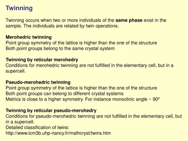
Twinning Twinning occurs when two or more individuals of the same phase exist in the sample. The individuals are related by twin operations. Merohedric twinning Point group symmetry of the lattice is higher than the one of the structure Both point groups belong to the same crystal system

E N D
Twinning Twinning occurs when two or more individuals of the same phase exist in the sample. The individuals are related by twin operations. Merohedric twinningPoint group symmetry of the lattice is higher than the one of the structureBoth point groups belong to the same crystal system Twinning by reticular merohedryConditions for merohedric twinning are not fulfilled in the elementary cell, but in a supercell. Pseudo-merohedric twinningPoint group symmetry of the lattice is higher than the one of the structureBoth point groups can belong to different crystal systemsMetrics is close to a higher symmetry. For instance monoclinic angle ~ 90º Twinning by reticular pseudo-merohedryConditions for pseudo-merohedric twinning are not fulfilled in the elementary cell, but in a supercell. Detailed classification of twins:http://www.lcm3b.uhp-nancy.fr/mathcryst/twins.htm
Posible twinning operations can be determined from group→ subgroup relations: G … point group of the structure H … point group of the crystal lattice Twinning operations: With twinning operations we can getindices of a selected reflection in all twin domains Decomposition of H to right classesaccording to G: - take element T1 of H which is not part of G - create set of elements GT1 (this is not necessarily subgroup)- find element T2 of H which is member neither of G nor of GT1 - create set of elements GT2- Finally H is decomposed to so called right classes. Each element of H belongs to one and only one right class. Each member of the right class can be taken as twinning operation.
Example: H = 4/mmm, G = mmm Order H is16, order G is 8 index of the twin is 2 a twin operation can be any from the following symmetry operations of H:
The operations give rise to m independent vectors. m=3 complete overlap 3 < m ≤ 3n partial overlap m=3n no overlap This classification will be explained with an example at the end of the lecture
Diffraction pattern combines intensities of twin individuals. The conditionsmeans that the argument of structure factor is always from the same right class of the decomposition. Otherwise the argument would “skip” between domains.
Fourier coefficients for twin Structure factors from all domains Structure factors from one domain (needed for calculation of Fourier map) The precision of “fraction” method grows with completing of the structure model If the Fourier map is not satidfactory switching the method may help
Merohedric Twinning Merohedric twinningPoint group symmetry of the lattice is higher than the one of the structureBoth point groups belong to the same crystal system Cubic system - possibilities for merohedric twinning: Red arrows indicate group - subgroup relations not induced by only loose of the centre of symmetry.
Example: H = 4/mmm, G = mmm Order H is16, order G is 8 index of the twin is 2 a twin operation can be any from the following symmetry operations of H: The eight operations are automatically derived and offered by group-subgroup tool of Jana2006
1. Selection of subgroup 2. Selection of twinning/expansion operator 3. Creating structure expanded to subgroup
Diffraction symmetry of a merohedric twin: The chance to recognize proper symmetry from the diffraction pattern of merohedric twin depends on the twin domains ratio. Lattice:4/mmm Structure:4/m Twin operation:none
For non-equal domains ratio the proper symmetry is still evident. Lattice:4/mmm Structure:4/m Twin operation:mx 2nd domain fraction:25%
For equal domains ratio false higher symmetry is detected. Lattice:4/mmm Structure:4/m Twin operation:mx 2nd domain fraction:50%
Pseudo-merohedric Twinning Pseudo-merohedric twinningPoint group symmetry of the lattice is higher than the one of the structureBoth point groups can belong to different crystal systemsMetrics is close to a higher symmetry - it mimics higher symmetry. For instance monoclinic angle ~ 90º
Pseudo-merohedric twinning without visible splitting of diffraction spots can also simulate false higher symmetry. Lattice:mmm Structure:2/m Monoclinic angle:≈ 90º Twin operation:none
For non-equal domains ratio the proper symmetry is still evident. Lattice:mmm Structure:2/m Monoclinic angle:≈ 90º Twin operation: mx 2nd domain fraction:25%
For equal domains ratio false higher symmetry is detected. Lattice:mmm Structure:2/m Monoclinic angle:≈ 90º Twin operation: mx 2nd domain fraction:50%
Pseudo-merohedric twinning without visible splitting of diffraction spots can be sometimes revealed by presence of strange systematic extinctions. Lattice:4/mmm Structure:mmm, Pmma cell parameters:a ≈ b Twin operation:none
For non-equal domains ratio the proper lattice symmetry is still evident but the proper systematic absences are hidden. Lattice:4/mmm Structure:mmm, Pmma cell parameters:a ≈ b Twin operation:4z 2nd domain fraction:25%
For equal domains ratio neither the proper lattice symmetry nor the proper systematic absences can be detected. However, ridiculous systematic absences can be used as a hint of twinning. Lattice:4/mmm Structure:mmm, Pmma cell parameters:a ≈ b Twin operation:4z 2nd domain fraction:50%
twin ratio ~ 0.5 twin ratio ~ 0.15
Solving successfully merohedric twin is like winning in a lottery!! Example: Fe2O3 or CrCoO3 No indication of split in the peak positions.
Solving successfully merohedric twin is like winning in a lottery!! Symmetry test shows that we are suspiciously close to orthorhombic symmetry. Twinning to be tested
Twinning of modulated crystals The twinning matrix is 3x3 matrix regardless to dimension.Twinning may decrease dimension of the problem. Example: La2Co1.7, Acta Cryst. (2000). B56, 959-971.Average structure: 4.89 4.89 4.34 90 90 120 , P63/mmcModulated structure: modulated composite structure, C2/m(a0g),6-fold twinning around the hexagonal c Reconstruction of (h,k,1.835) from CCD measurement.
Usually splitting of diffraction spots is clearly visible.Y(HP2O7)(H2O)3 Cell parameters: 6.422 6.890 9.817 81.65 80.27 88.35; symmetry: P-1 Twinning matrix: -1.0000 0.0517 0.0000 0.0000 1.0000 0.0000 0.0000 0.4161 -1.0000 (h’ = M*h, h is a column) Rot= 180.21º around 0.0135 0.9994 -0.0318 (direct space)
0,8,8 I 60 40 20 ω 0 24.6 25.0 25.4 25.8 26.2 Sometimes the splitting is tiny.In this case it would be hidden for normal CCD measurement. NiCd(CN)4O3 Cell parameters: 8.522 16.012 7.651 90 90.32 90 Symmetry: C2/c(α0γ)0s q vector (0.4346, 0, 0.13) Twinning matrix: Transformed indices: Almost complete overlap of main reflections, clear separation of satellites.
Refinement of pseudo-merohedric twins with split reflections • Neglecting of all but 1st twin domainsWorks fine when there is not too much fully overlapped reflections • Using 1st domain + twinning matrixThis scales the fully overlapped reflections • Using all domains + twinning matrix + some criterion for overlapsJana2000 uses angular difference limits. It is designed for point detector data but surprisingly it also works for most CCD cases • Using all domains + HKLF5 data
Alternative indexing of twins Twins can be indexed using three or more reciprocal vectors The operations give rise to m independent vectors. m=3 complete overlap, merohedric twinning 3 ≤ m ≤ 3n partial overlap m=3n no overlap
Example for triclinic pseudo-merohedric twin Tb(HP2O7).3H2O(Acta Cryst. E63, i87-i88) Cell parameters:6.455 6.960 9.825 81.62 80.46 88.34 Twinning operation: rotation 180º around b. T applies to indices as a column, therefore T inverted transposed will apply to reciprocal base vectors as a column. For two fold twin T-1 = T.
T applies to indices as a column, therefore T inverted transposed will apply to reciprocal base vectors as a column. For two fold twin T-1 = T. The twinning operation yields one new reciprocal vector: We can index the complete diffraction pattern using four indices h,k,l,m. The first twin individual will have indices h,k,l,0; the second twin individual will have indices –h,m,-l,0. The relationship between the individuals can be expressed by 4x4 matrix:
In a formal way this is a description of non-modulated composite structure. Symmetry: P-1(abg)00Cell parameters: 6.455 6.960 9.825 81.62 80.46 88.34q-vector: (0.0537 1 0.4114)W-matrix: as given aboveStructure in both composite part: 3d structure of Tb(HP2O7).3H2Obecause the W matrix does not change the elementary cell Activation of composite description in Jana2006.
Refinement of Tb(HP2O7).3H2O as a classical twin: Twin fraction: 0.5 Refinement of Tb(HP2O7).3H2O as a composite structure: The difference is caused by summing structure factors in composite structure instead of intensities in a twin. This is experimental prove that the twin individuals of our structure diffracted independently. With twin fraction ≠ 0.5 we would have another prove since in a common structure an independent scaling would not be possible.
Visualization of electron density Refine creates M80M80 is used by Fourier for calculation (it does not need M40, M90)Contour plots section through the electron density maps M80 is created only when Refine finishes regularly! Fourier can be started from Jana basic window (icon Fourier) or from Contour program (button New plot).
Fourier options Shape function: 1 for all collected reflections Checking Fourier: for refined or simulated structure (On the right: two ways how to simulate data)
“Explicit scope” calculates a parallelepiped based on fraction coordinates. The map orientation says which two dimensional plot will be plotted by Contour. In this case Countour will plot x-y sections stacked along z
“Scope by central point” calculates a parallelepiped based on a central point and dimensions (in Å) along first, second and third axis. In this example the central point is atomic position of Ni1. The first axis is y, second axis z, third axis x. Contour will plot x-z sections stacked along x. The size of the sections will be 6x6 Å and they will be centered in Ni1 position. The number of sections along x will be 2/0.02.
After calculation of electron density map according to the settings given in the previous slide Contour show the following dialogue: “Use old map” plots the already calculated Fourier map.“Calculate new ones” opens Fourier options and then calculates new Fourier map“Draw maps as calculated” uses size and orientation of the pre-calculated maps“Draw a general section” creates new set of 2d planes in user-defined orientation
“Use old maps” - “Draw maps as calculated”: Plots the first section in previously defined orientation
“Atoms edit” plots Ni1 Explanation of another buttons …..
Sum ON/OFF Sum ON merges all the section into one section. Applications: modulation functions, looking for difference maxima of smeared atoms etc.
The section 6x6 Å will be stacked in the direction perpendicular to the plane O2-O3-O4. O2 will be in the centre of plot; The vector O2->O3 will be horizontal; The second vector will complete a right-handed system and will belong to the plane O2-O3-O4. Whether O3 and O4 positions are present in the plot depends on the scope.
The Fourier map must cover the asymmetric unit. The new map can be arbitrarily expanded.
The selected section with O2 (in the middle), O3 (on the right) and O4 (top). The section can be summed. The contour step can be changed to reveal more details. We can click on the map and see neighboring atoms. etc.
The same section with different contour step. The neighboring atoms shown when we click in the middle of the strongest maximum. The code for symmtry positions can be used in definition of general section: they can be found here or in the listing of Dist (when “symmetry codes” are activated in Dist options.