Download
1 / 36
360 likes | 528 Views
Space Based Solar Power Satellite Conceptual Design for Retrodirective Control. Space Engineering Institute Spring 2009. Overview. Creating a satellite module that will be attached to a Japanese experimental satellite in a Low-earth orbit.

E N D
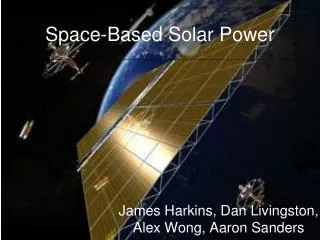
Space Based Solar Power Satellite Conceptual Design for Retrodirective Control Space Engineering Institute Spring 2009
Overview • Creating a satellite module that will be attached to a Japanese experimental satellite in a Low-earth orbit. • Our team objective is to create a satellite module that can test the retrodirective beam control method of sending microwave power back to Earth. • The module must provide its own power, and have its own thermal management systems.
Module System Sandwich Design Space Environment & Orbit Photovoltaic Cells Thermal Management Structures & Materials Energy Storage & Power Conversion Antenna Array Retrodirective Control logic
Semester Goals and Expectations • Become familiar with Satellite Tool Kit software • Model a cubic satellite and evaluate solar energy collected at each of its six faces to identify the optimum location for the solar panels • Determine the maximum, minimum, and average solar energy collected on the optimum location during one orbit
Satellite Orientation • Orange-North • Green- South • White- Nadir • Yellow-Zenith • Purple-Leading • Teal- Trailing
Satellite Orbit Options • Geostationary • Altitude: 35,786 km • Inclination: 0º • Low Earth Orbits • Critically Inclined Sun Synchronous: • Perigee altitude: 400 km • Retrograde inclination: 116.565º • Circular: • Altitude: 500 km • Inclination: 45º • ETS-VII: Japanese satellite with similar initial conditions • Altitude: 550 km • Inclination 35º
Energy and Power Received • Power α cos(θ) • θ= angle between the sun vector and the vector pointing normal to the face • Units: [W/m2] • Energy=Power*Time • Units: [J/m2] • Also dependent on the cosine of θ http://solar.mridkash.com/wp-content/uploads/cosine-law.jpg
Approach • STK provides angular data for each face of the cubic satellite • Angular data are converted to power [W/m^2] • Power data are converted to energy data [J/m^2]
Data from STK The Zenith, Nadir, Leading and Trailing faces have approximately the same exposure to the sun. The antenna will be located on the Nadir face, so it reasonably follows that the solar panels be placed on the Zenith face, directly opposite the antenna. A circular orbit with an altitude of 500 km and inclination of 45° was chosen, because with the options available, this orbit allows the solar panels to receive the most sunlight.
Thermal Management Objective • To perform thermal analysis of the satellite and ensure a suitable operating environment for the payload. • Tools • Thermal Desktop software Research Topics • Low earth orbit environment • Temperature requirements for internal components • Cooling/heating methods
External Environment In LEO, the satellite will be heated by: • Direct sunlight • Earth’s albedo • Earth’s IR emittance The total heat absorbed by the satellite will not remain constant. Fluctuations occur due to: • Entering/exiting Earth’s shadow • Varying surface conditions on Earth
Satellite Interior The interior environment of the satellite must be kept at a proper temperature range. Most electronic equipment onboard must operate in a surrounding temperature range of 0 to 50 degrees Celsius. Factors to consider for the internal energy balance: • Fluctuating external heat rates • Heat released by electronic equipment -Low level baseline operation -High level during periodic transmission • Thermophysical properties of structural material
Cooling/Heating Methods External • Radiators: Do not require energy. Release heat without re-entry (thermal diode) Internal • Thermoelectric Coolers/Heaters: Require energy. Can absorb/emit heat by reversing polarity • Mechanical cooling: Expander, compressor, or heat exchanger. Takes up space and weight. • Resistive Heating:Requires energy but elements are compact in size. • Heat Pipes: Passive
Thermal Desktop Objectives • Develop a model for the satellite module. • Use the orbital information from STK to determine thermal environment of the satellite. Progress • In process of creating models.
Thermal Desktop, Continued Example of absorbed flux from sun, earth’s albedo and IR emittance.
Structural Requirements The satellite must have ability to: • Withstand launch loads • Provide desired rigidity • Protect sensitive payload components from extreme temperatures.
Material Selection Currently evaluating two different materials: Ti6Al4V Titanium alloy VS. Aluminum Alloy( 7075-T651) Although Titanium is 60% heavier than Aluminum, it is over twice as strong. Possibility of having titanium based honey comb exterior; joined by a smaller portion of aluminum interior.
Honeycomb Layer • Planned use of “Honeycomb” design: • Hexagonal Structure • Uses the least amount of material to create a lattice of cells within a given volume • Maintains strength
Preliminary Sandwich Structure Layered design that takes advantage of each materials different thermal properties.
Goal & Requirements • Collect Solar Energy and store it to power the RF amplifiers • Collect power from 1m2 solar panel. • Store energy in a medium that can withstand high drain current. • Energy storage mediums must have a wide operating temperature range.
DC to RF Converter Options Tube magnetron @ 5.8 GHz • Can output 650W with 65% efficiency • Heavier than solid state options • (1.1kg vs .6g) • Produces more heat than solid state converters • Requires a high voltage power supply to excite the electrons. GaN HEMT solid state converters @ 5.8 GHz • Fujitsu converter can output 320W theoretically • Cree converter can output 35W, commercially available now. • Lightweight (.6 g) and extremely small size relative to the magnetron.
Energy Storage – Li-ion • For storing energy from the photovoltaic cells Li-ion and Li-S batteries are being considered. • Li-ion batteries have an energy density of 110 Wh/kg. • Saft MPS space series batteries that are already thermally insulated and autonomously heated. • Have a wide operating temperature range ( -5o F to 140o F for charging and -40o F to 140o F in operation) • Built in over current and charging circuits into the module. • 17 Ah capacity per battery @ 28V.
Energy Storage - Continued • Lithium sulphur batteries are being considered for their higher energy density (350 Wh/kg vs the 110Wh/kg for Li-Ion) • Experimental, expensive technology. • No history of satellite use. • Ultracapacitors • High energy density capacitor used for powering the Solid state microwave converters when transmitting a signal. • Ultracapacitors can handle 20A continuous current. • Will be used in conjunction with the Li-ion batteries to power the GaN HEMT amplifiers at their maximum capacity
Current Concept • Maximum Power Point Tracker monitors the voltage and current of the Solar Panel and tracks the peak point on the power curve. • Battery Management System tracks the charge rate, voltage and current.
Retrodirective Beam Control • The implementation of retrodirective beam control is critical to accurate beam pointing, as well as the overall safety of the system. • The key objective is to have the power beam of the solar power satellite’s transmitter pointedonlyin the direction of a received pilot beam, which provides a phase reference • Retrodirective beam control ensures that microwave power transmission is both safe and insusceptible to accidental misalignment.
Proposed Retrodirectivity Method • The 2.9 GHz incoming pilot signal is received at a Frequency of ω1 and Phase φ1 • To conjugate, the received signal is next mixed with a reference source of Frequency2ω1 and Phase φref • The conjugated signal is then mixed itself to produce a signal with Frequency 2ω1 and Phase -2φ1 • After conjugated and doubled, the signal is transmitted from a different transmitting subarray • The complete phased array transmits a 5.8GHz beam in the direction of the incoming pilot signal
Proposed Phased Array Antenna Concept • Linear Microstrip Patch Phased Array Antenna • The Microstrip Patch Antenna will operate at a Frequency of 5.8 GHz, and will have an Input Impedance of 50Ω • The Antenna’s design features a 4x4 Phased Array consisting of 15 Transmitting Elements and 1 nested Receiving Element each spaced 0.5λ apart • The 4 subarrays are expected to be at different phases prior to power transmission 5.8 GHz 4x4 Linear Microstrip Patch Phased Array with nested 2.9 GHz Receiving Element
Antenna and Transmitter Interface • Magnetron • RF power is split to feedfed to each antenna subarray • Negligible power loss may occur during energy feed • Loss expected from phase shifter • Solid-State • Facilitates electronic beam steering • Power amplifier and phase shifter are placed behind each transmitting element • Microwave filters are required to countervail amplifier-spawned noise
Advantages of Proposals Microstrip Patch Antenna • Advantages • Low cost to manufacture • Light weight and low profile • Supports both Linear and Circular Polarization Retrodirectivity Method • Advantages • Conjugates pilot signal directly at RF • Reduction in the number of electronics per antenna subarray • Less power consumption