Download
1 / 51
510 likes | 640 Views
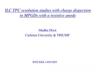
Alain Bellerive Madhu Dixit Carleton University. CERN 10-11 September, 2007. TPC Readout Development with Charge Dispersion Signal. Outline. Principle of Charge Dispersion Signal with MPGD Recent Results Applications: ILC & T2K & EXO Simulation Framework Summary.

E N D
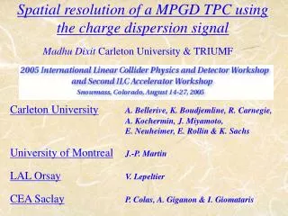
Alain Bellerive Madhu Dixit Carleton University CERN 10-11 September, 2007 TPC Readout Development with Charge Dispersion Signal Alain Bellerive
Outline • Principle of Charge Dispersion Signal with MPGD • Recent Results • Applications: ILC & T2K & EXO • Simulation Framework • Summary Alain Bellerive
Motivation and Principle Alain Bellerive
Proportionalwire Micro PatternGas Detector Anode pads Cathode pads width w width w For small diffusion, less precise centroid for wide pads Accurate centroid determination possible with wide pads Direct signal on the MPGD anode pad Induced cathode signal determined by geometry • The physics limit of TPC resolution comes from transverse diffusion: Neff = effective electron statistics. • For best resolution, choose a gas with smallest diffusion in a high magnetic field Diffusion sets the fundamental limit on achievableTPC resolution Pad width would limits MPGD TPC resolution ExB systematics limits wire/pad TPC resolution Alain Bellerive
Charge dispersion in a MPGD with a resistive anode • Modified GEM anode with a high resistivity film bonded to a readout plane with an insulating spacer. • 2-dimensional continuous RC network defined by material properties & geometry. • Point charge at r = 0 & t = 0 disperses with time. • Time dependent anode charge density sampled by readout pads. • Equation for surface charge density function on the 2-dim. continuous RC network: (r) Q (r,t) integral over pads mm ns r / mm Alain Bellerive
The proof - a 6 keV 55Fe x-ray photon event as seen in our first GEM test cell with a resistive anode Collimator size ~ 1 mm ; signal detected by ~7 anodes (2 mm width) Alain Bellerive
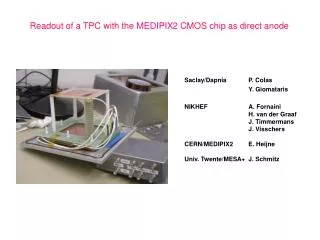
Micromegas with a resistive readout Alain Bellerive
Charge dispersion signals for the GEM readoutSimulation vs. measurement for Ar+10%CO2 (2 x 6 mm2 pads) Collimated ~ 50 m 4.5 keV x-ray spot on pad centre. Difference = induced signals (MPGD '99, Orsay & LCWS 2000) were not included in simulation). Primary pulse normalization used for the simulated secondary pulse Simulated primary pulse is normalized to the data. Alain Bellerive
Initial B=0 Cosmic Ray Tests in Canada • 15 cm drift length with GEM or Micromegas readout • Ar+10% CO2 chosen to simulate low transverse diffusion in a magnetic field. • Aleph charge preamps. Rise= 40 ns, Fall = 2 s, • 200 MHz FADCs rebinned to digitization effectively at 25 MHz. • In contrast to normal practice, we use digitized preamp pulse with no shaping so as not to lose electron statistics. The resolution was next measured with a charge dispersion resistive anode readout with a double-GEM & with a Micromegas. The GEM-TPC resolution was first measured with conventional direct charge TPC readout. Alain Bellerive
GEM TPC charge dispersion simulation (B=0) Cosmic ray track, Z = 67 mm Ar+10%CO2 2x6 mm2 pads Simulation Data Centre pulse used for normalization - no other free parameters. Alain Bellerive
Charge dispersion pulses & pad response function (PRF) • Non-standard variable pulse shape; both the rise time & pulse amplitude depend on track position. • The PRF is a measure of signal size as a function of track position relative to the pad. • We use pulse shape information to optimize the PRF. • The PRF can, in principle, be determined from simulation. • However, system RC non-uniformities & geometrical effects introduce bias in absolute position determination. • The position bias can be corrected by calibration. • PRF and bias determined empirically using a subset of data used for calibration. Remaining data used for resolution studies. Alain Bellerive
GEM & Micromegas PRFs for tracksAr+10%CO2 2x6 mm2 pads The pad response function amplitude for longer drift distances is lower due to Z dependent normalization. GEM PRFs Micromegas PRFs Micromegas PRF is narrower due to the use of higher resistivity anode & smaller diffusion than GEM after avalanche gain Alain Bellerive
Results Alain Bellerive
B=0 Cosmic Ray Transverse Resolution Ar+10%CO2 R.K.Carnegie et.al., NIM A538 (2005) 372 K. Boudjemline et.al., NIM A - in press A. Bellerive et al, LCWS 2005, Stanford Compared to conventional readout, charge dispersion gives better resolution for the GEM and the Micromegas. Alain Bellerive
KEK beam test in a magnet at 1 T Canadian/French & Japan/German TPCs • 4 GeV/c hadrons (mostlyπs) • 0.5 & 1 GeV/c electrons • Super conducting 1.2 T magnet without return yoke • Inner diameter : 850 mm • Effective length: 1 m Canadian TPC in the beam outside the magnet Alain Bellerive
Track display -Ar+5%iC4H10Micromegas 2 x 6 mm2 pads B = 1 T Zdrift = 15.3 cm main pulse Alain Bellerive
Transverse spatial resolution Ar+5%iC4H10 E=70V/cm DTr = 125 µm/cm (Magboltz) @ B= 1T Micromegas TPC2 x 6 mm2 pads- Charge dispersion readout 4 GeV/c + beam ~ 0°, ~ 0° • Strong suppression of transverse diffusion at 4 T. Examples: DTr~ 25 m/cm (Ar/CH4 91/9) Aleph TPC gas ~ 20 m/cm (Ar/CF4 97/3) Extrapolate to B = 4T Use DTr = 25 µm/cm Resolution (2x6 mm2 pads) Tr 100 m (2.5 m drift) s0= (52±1) mm Neff = 220 (stat.) Alain Bellerive
Extrapolation confirmed in 5 T cosmic tests at DESYCOSMo (Carleton, Orsay, Saclay, Montreal) Micromegas TPC DTr= 19m/cm, 2 x 6 mm2 pads ~ 50 m av. resolution over 15 cm (diffusion negligible) 100 m over 2 meters looks within reach! Nov-Dec, 2006 Alain Bellerive
Applications Alain Bellerive
TPC (B=4T) TPC (B=3T) Silicon (B=5T) TPC (B=3.5 T) TPCtracker part of 3 present ILC detector concepts Alain Bellerive
Demonstration phase ILC TPC R&D • Canada has been involved from the beginning • 2 mm x 6 mm pads (1,500,000 channels) for the readout with GEMs or Micromegaswereproposed initially • For the GEM, large transverse diffusion in the transfer & induction gaps provides a natural mechanism to disperse the charge and facilitate centroid determination. • The GEM will still need ~ 1 mm wide pads to achieve ~ 100 m resolution goal with ~3,000,000 readout channels • Even narrower pads would be needed for the Micromegas Development of the new concept of charge dispersion in a MPGD with a resistive anode makes position sensing insensitive to pad width The technique works for both the GEM and the Micromegas Charge dispersion concept to reduce #channels and hence cost Alain Bellerive
Preparing the detector for physics at ILC • A formal Linear Collider TPC (LC-TPC) collaboration recently formed • Formal review of tracking systems at Beijing - First TPC assignment construct a 1 meter prototype & comprehensive beam tests in a 4 T magnet in a beam with ILC like time structure with realistic electronics by 2010 in time to write detector EDR. • Test two possible readout options being developed • GEM with 1 mm pads • 2) Micromegas with 2 mm pads with charge dispersion readout Alain Bellerive
1 meter Large Prototype TPC being developed for 1 T tests at DESY (2008) & 4 T tests at Fermilab (2010) 7 panels ~ GEMs with 1 mm pads and Micromegas with 2 mm wide pads Up to 10,000 instrumented channels Alain Bellerive
T2K Near Detector - TPC Building T2K TPC prototype at TRIUMF Alain Bellerive
Application to T2K TPC • 7x9 mm2 pads • 10% p/p (1 GeV/c) • Good enough • Requirement limited by Fermi motion Partnership between CARLETON & CEA/DAPHNIA From a talk by F.Sánchez (Universitat Autònoma de Barcelona) But better momentum resolution would be useful: Better background rejection = More channels => $$? Can one do it with the presently chosen pad dimensions? Alain Bellerive
T2K simulation for 8 x 8 mm2 padsTrack crosses no pad row or column boundariesAr+10% CO2 , vDrift = 28 m/ns (E = 300 V/cm) Aleph preamp tRise = 40 ns, tFall = 2 s Anode surface resistivity 150 K/, dielectric gap = 75 m Track at z = 175 mm, x = 0, = 0 (uniform ionization) (ns) (ns) Alain Bellerive
Pad response function Relative amplitude -20 -10 0 10 20 Micromegas TPC with resistive readout - Simulated PRF8 x 8 mm2 pads, Ar+10% CO2@ 300 V/cm, 175 mm drift distance (mm) Alain Bellerive
EXO at SNOLAB Possible concept for a gas double beta counter Anode Pads Micro-megas WLS Bar Xe Gas Isobutane TEA Electrode Lasers . . . . . . . . . . . . . . . . Grids PMT For 200 kg, 10 bar, box is 1.5 m on a side Alain Bellerive
Simulation Alain Bellerive
MC Simulation – Resolution & PRF diffusion dominant noise pad-pitch dominant Ar/iC4H10 95/5 Micromegas sx / mm w/121/2 = 664 mm electron mesh avalanche anode pads z / cm x Direct signal 14 < z < 15cm TPC 12 < z < 13cm PRF 10< z < 11cm relative amplitude 15.7 cm 8 < z < 9cm 6 < z < 7cm 4 < z < 5cm 2 < z < 3cm 0 < z < 1cm Alain Bellerive xpad-xtrack / mm
Transverse Spatial Resolution 2 mm track f = 10° s = 54 mm clusters 4 mm s = 89 mm 6 mm 2 mm track f = 10° s = 120 mm s = 54 mm clusters track f = 10° clusters y 8 mm 2 mm 2 mm s = 54 mm y 6 mm s = 54 mm track f = 10° 4 mm y 4 mm 4 mm clusters s = 89 mm s = 89 mm 6 mm 2 mm y s = 120 mm 0 0 0 x 0 0 8 mm x 0 x 0 x 0 s = 145 mm 2 mm 2 mm 2 mm 2 mm Khalil Boudjemline IEEE, 2006 Nuclear Science Symposium Ionization Statistics & Angle Effect Monte Carlo Simulation Ar/iC4H10 95/05B = 1 T x (mm) Alain Bellerive
Movable source holder Contacts rings with wiper Field Rings Source Grid Anode Gridded Ion Chamber Progress on energy resolution Pure Xe, 2 Bar s = 0.6% with pattern reco based on MC Alpha spectrum at 2 b pressure. Alain Bellerive
Simulation of TPC • The standard is to use G4 for the definition of geometry and material • Maps for E & B fields • Use of the standard EM package • Ionization at fixed intervals (~10 μm) • Break out of G4 to drift clusters to readout pads • Several groups uses different software packages: EXO, ILC/TPC, T2K, etc… WHY NOT HAVING A COMMON FRAMEWORK EMBEDED WITHIN G4 ?!? Alain Bellerive
Incorporate 1) ionization statistics & transport in G4 based on GARFIELD 2) signal & avalanche in G4 based on GARFIELD 3) new cluster object in G4 (faster) New Initiative G4 geometry and material GARFIELD geometry voltages E field map G4 ionization and transport MAGBOLTZ transport tables Gas Properties Transport HEED ionization pattern G4 readouts Signals Alain Bellerive
Conclusion Alain Bellerive
A standard MPGD-TPC cannot get good resolution with wide pads • With charge dispersion, wide pads can be used without sacrificing resolution. Charge dispersion works both for GEM and Micromegas. • At 5 T, an average ~ 50 m resolution has been demonstrated with 2 x 6 mm2readout pads for drift distances up to 15 cm. • The ILC-TPC resolution goal ~100 m for all tracks up to 2 m driftappears feasible. • Canadian responsibilities for large 1 m prototype tests to 2010: Construct seven large Micromegas panels with charge dispersion shared with France (Carleton & Montréal) • Application to T2K: R&D France/Canada • Development of common simulation framework for TPC • Ionization and transport in G4 [via Garfield capabilities] Summary Alain Bellerive
Extra Slides Alain Bellerive
No ExB effects in MicroPattern Gas Detectors (MPGD)GEM a thin film proportional detector Gas gain in narrow channels with high electric field 300-400V a Thin ~ 50 mm double-sided copper clad Kapton foil Matrix of 50-70 mm diameter channels ~ 140 mm pitch Up to 80 kV/cm electric field inside channels Alain Bellerive
Micromegas - A small gap parallel plate proportional detectorMicromesh supported by ~ 50 m pillars above anode Alain Bellerive
Track PRFs with GEM & Micromegas readout The PRFs are not Gaussian. The PRF depends on track position relative to the pad. PRF = PRF(x,z) PRF can be characterized by FWHM (z) & base width (z). PRFs determined from the data parameterized by a ratio of two symmetric 4th order polynomials. a2 a4 b2 & b4 can be written down in terms of and & two scale parameters a & b. Alain Bellerive
Pad Response Function / Ar+5%iC4H10Micromegas+Carleton TPC 2 x 6 mm2 pads, B = 1 T 30 z regions / 0.5 cm step 0 < z < 0.5 cm 0 .5 < z < 1 cm 1 < z < 1.5 cm 1.5 < z < 2 cm 2 < z < 2.5 cm 2.5 < z < 3 cm 3 < z < 3.5 cm 3.5 < z < 4 cm 4 < z < 4.5 cm 4.5 < z < 5 cm 5 < z < 5.5 cm 5.5 < z < 6 cm normalized amplitude 6 < z < 6.5 cm 6.5 < z < 7 cm 7 < z < 7.5 cm 7.5 < z < 8 cm 8 < z < 8.5 cm 8.5 < z < 9 cm Alain Bellerive xtrack – xpad / mm 4 pads / ±4 mm
Pad Response Function / Ar+5%iC4H10 9 < z < 9.5 cm 9.5 < z < 10 cm 10 < z < 10.5 cm 10.5 < z < 11 cm 11 < z < 11.5 cm 11.5 < z < 12 cm normalized amplitude 12 < z < 12.5 cm 12.5 < z < 13 cm 13 < z < 13.5 cm 13.5 < z < 14 cm 14 < z < 14.5 cm 14.5 < z < 15 cm xtrack – xpad / mm 4 pads / ±4 mm PRF parameters • a = b = 0 • = base width = 7.3 mm • = FWHM = f(z) The parameters depend on TPC gas & operational details Alain Bellerive
6 mm 2 mm Track fit using the the PRF Track at: xtrack= x0+ tan() yrow Determine x0 &by minimizing2 for the entire event • Definitions: • - residual: xrow-xtrack • bias: mean of xrow-xtrack = f(xtrack) • resolution: standard deviation of residuals Alain Bellerive 43
Bias for inner rows bias after ± 20 mm Residual / mm row 3 bias before row 4 row 5 xtrack / mm Alain Bellerive
Beam test motivations VD = 26.73 mm/ns VD = 22.75 mm/ns E = 70 V/cm E = 300 V/cm CD = 126 mm/cm1/2 CD = 223 mm/cm1/2 E = 70 V/cm E = 300 V/cm Alain Bellerive
Transverse Spatial Resolution TPC q z 4 GeV/c + beam ~ 0°, ~ 0° Carleton TPC (2 x 6 mm2 pads) Ar/CO2 90/10B = 0 TCD = 211 mm/cm1/2 Carleton TPC (2 x 6 mm2 pads) Gain = 3500 track s0= (64±4) mm Neff = 261 (stat.) f Ar/iC4H10 95/05B = 1 TCD = 126 mm/cm1/2 pad plane s0= (50±2) mm Neff = 22 0 (stat.) Gain = 8000 Alain Bellerive
Transverse Spatial Resolution Khalil Boudjemline IEEE, 2006 Nuclear Science Symposium Angle effect Ar/iC4H10 95/054 GeV/c + beam ~ 0°, B = 1 T, CD = 126 mm/cm1/2 Carleton TPC (2 x 6 mm2 pads) s0= (178±4) mm Neff = 3210 (stat.) f = 0° f = 10° track s0= (52±3) mm Neff = 211 (stat.) pad plane Alain Bellerive
Transverse Spatial Resolution 11.0° < |f| < 14.0° 8.0° < |f| < 11.0° 8.0° < |f| < 11.0° 5.0° < |f| < 8.0° 5.0° < |f| < 8.0° 5.0° < |f| < 8.0° 1.5° < |f| < 5.0° 1.5° < |f| < 5.0° 1.5° < |f| < 5.0° 1.5° < |f| < 5.0° |f| < 1.5° |f| < 1.5° |f| < 1.5° |f| < 1.5° |f| < 1.5° Angle effect Ar/iC4H10 95/05Cosmics ~ 0°, B = 0 T, CD = 223 mm/cm1/2 Carleton TPC (2 x 6 mm2 pads) f range track Cosmics pad plane Alain Bellerive
TPC R&D for the ILC - a world wide effort Alain Bellerive