Download
1 / 18
180 likes | 307 Views
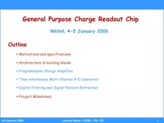
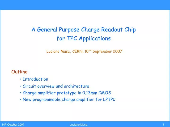
A General Purpose Charge Readout Chip for TPC Applications Luciano Musa, CERN, 10 th September 2007. Outline Introduction Circuit overview and architecture Charge amplifier prototype in 0.13mm CMOS New programmable charge amplifier for LPTPC. Digital Circuit.

E N D
A General Purpose Charge Readout Chip for TPC Applications Luciano Musa,CERN, 10th September 2007 • Outline • Introduction • Circuit overview and architecture • Charge amplifier prototype in 0.13mm CMOS • New programmable charge amplifier for LPTPC
Digital Circuit Alice TPC FEE – MWPC Readout Front End Electronics Architecture FEC (Front End Card) - 128 CHANNELS (CLOSE TO THE READOUT PLANE) DETECTOR Power consumption: < 40 mW / channel L1: 5ms 200 Hz 8 CHIPS x 16 CH / CHIP 8 CHIPS x 16 CH / CHIP drift region 88ms L2: < 100 ms 200 Hz ALTRO gating grid PASA ADC RAM anode wire DDL (3200 CH / DDL) CUSTOM IC (CMOS 0.35mm) pad plane 570132 PADS CUSTOM IC (CMOS 0.25mm ) CSA SEMI-GAUSS. SHAPER 1 MIP = 4.8 fC S/N = 30 : 1 DYNAMIC = 30 MIP • BASELINE CORR. • TAIL CANCELL. • ZERO SUPPR. 10 BIT < 10 MHz MULTI-EVENT MEMORY GAIN = 12 mV / fC FWHM = 190 ns
PASA CHIP Power Regulation Board Controller (FPGA) 17 cm ALTRO CHIP 19 cm Alice TPC FEE – MWPC Readout 128-channel Front End Card Top Side
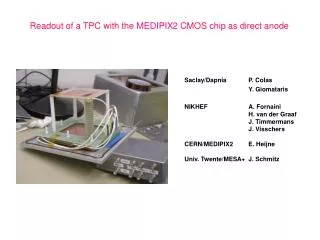
A general purpose charge readout chip number of channels: 32 or 64 programmable charge amplifier sensitive to a charge in the range: ~102- ~107 electrons Input capacitance: 0.1pF to 10pF Peaking time: 20ns – 100ns high-speed high-resolution A/D converter sampling rate: 40MHz programmable digital filter for noise reduction and signal interpolation; a signal processor for the extraction and compression of the signal information (charge and time of occurrence). Programmable readout chip for MPGD
Anti-Aliasing Filter Anti-Aliasing Filter Anti-Aliasing Filter Signal Processor Signal Processor Signal Processor Data Compression Data Compression Data Compression Multi-Acq Memory Multi-Acq Memory Multi-Acq Memory Charge Amplifier Charge Amplifier Charge Amplifier ADC ADC ADC I N T E R F A C E Hit Finder • Maximize S/N • reduce quantization error • reduce signal bandwidth • Correct for crosstalk and common mode noise • Optimum pulse shaping for extraction of pulse features Feature Extaction Histogrammer Charge Readout Chip Block Diagram 32 / 64 Channel
H(s) H(s) H(s) H(s) H(s) H(s) OPA OPA < 1mV Noise < 103 e 30mV MIP = 3x10⁴ e Q Q/Cf Prototype Architecture Cf OPA Cd Shaping Amplifier Architecture • Single Ended Charge Sensitive Amplifier • Nonlinear Pole Zero Cancellation • 2 Shaping Amplifiers • Fully differential Rail to Rail Output Amplifier • Driving Capability: 30 pF • Optimized for one Signal Polarity
5 versions 7 standard channels Programmable Charge Amplifier Gerd Trampitsch INPUTS Production Engineering Data • 12- channel 4th order CSA • various architectures (classical folded cascode, novel rail-to-rail amplifier) • process: IBM CMOS 0.13 mm • area: 3 mm2 • 1.5 V single supply • Package: CQFP 144 • MPR samples (40): Apr ‘06 single channel OUTPUTS
Fit with G4 function Prototype Measurements • 4th Order Semi Gaussian Pulse • Peaking Time 100 ns – Standard Channel • 4th Order Semi Gaussian Fit A(t / t)4e-4(t/t)
Programmable Charge Amplifier Programmable Charge Amplifier submitted in May 06 • 1.5 V Supply, power consumption < 8 mW / channel • 16 channel charge amplifier + anti-aliasing filter • Single ended preamplifier • Fully differential output amplifier • Both signal polarities • Power down mode (wake-up time = 1 ms ) • Programmable peaking time (30 ns – 120 ns) – 3rd order semi Gaussian pulse shape • Programmable gain in 4 steps (12 – 27 mV/fC) • Preamp_out mode
Programmable Charge Amplifier • Programmable Peaking Time • 30 to 120 ns
Programmable Charge Amplifier • Programmable Gain (120 ns peaking time) • Peaking time is nearly insensitive to different gain settings • 12, 15, 19, 27 mV/fC
Programmable Charge Amplifier • Programmable Gain (30 ns peaking time) • Peaking time is nearly insensitive to different gain settings • 11, 14, 18, 25 mV/fC
Programmable Charge Amplifier • Linearity • Nonlinearity < 1% up to 160 fC
Programmable Charge Amplifier • Preamp_out mode • Programmable rise time (10 ns to 80 ns)
Programmable Charge Amplifier • Preamp_out mode • Programmable gain (5.3 mV/fC to 6.8 mV/fC)
Programmable Charge Amplifier • Preamp Decay Time • Preamp_out mode • Continuously programmable
Milestone I ⇒ Programmable Charge Amplifier (prototype) 16 channel charge amplifier + anti-aliasing filter Milestone II ⇒ 10-bit ADC (prototype) 4-channel 10-bit 40-MHz ADC. The circuit can be operated as a 4-channel 40-MHz ADC or single-channel 160-MHz ADC Milestone III ⇒ Charge Readout Chip (prototype) This circuit incorporates 32 (or 64) channels. Milestone IV ⇒ Charge Readout Chip (final version) Project Milestones