Download
1 / 23
330 likes | 885 Views
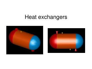
Heat Exchange between two fluids that are at different temperatures and separated by a solid wall. Specific applications include: space heating and air-conditioning, power production, waste heat recovery, and chemical processing. Heat Exchanger Types

E N D
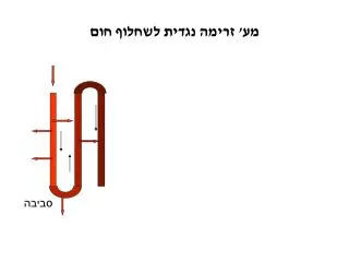
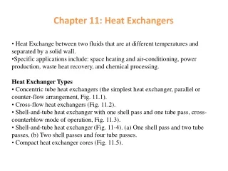
Heat Exchange between two fluids that are at different temperatures and separated by a solid wall. • Specific applications include: space heating and air-conditioning, power production, waste heat recovery, and chemical processing. • Heat Exchanger Types • Concentric tube heat exchangers (the simplest heat exchanger, parallel or counter-flow arrangement, Fig. 11.1). • Cross-flow heat exchangers (Fig. 11.2). • Shell-and-tube heat exchanger with one shell pass and one tube pass, cross-counterblow mode of operation, Fig. 11.3). • Shell-and-tube heat exchanger (Fig. 11-4). (a) One shell pass and two tube passes, (b) Two shell passes and four tube passes. • Compact heat exchanger cores (Fig. 11.5). Chapter 11: Heat Exchangers
hot fluid Ah q T∞,h, hh δ wall T∞,c, hc Ac cold fluid Ts,h Ts,c T∞,c T∞,h Rw or THE OVERALL HEAT TRANSFER COEFFICIENT
An overall heat transfer coefficient, analogous to Newton’s law of cooling, is introduced, THE OVERALL HEAT TRANSFER COEFFICIENT For a heat exchanger, fins are often added to surfaces exposed to either or both fluids. Surfaces are also subject to fouling by fluid impurities, rust formation, or other reactions between the fluid and the wall material. The subsequent deposition of a film or scale on the surface can greatly increase the resistance to heat transfer between the fluids.
THE OVERALL HEAT TRANSFER COEFFICIENT For a plat surface without fins: For a surface with fins: So , in the expressions for a flat surface, replacing by to obtain the expression for a surface with fins: For fouling , introduce an additional thermal resistance, termed the fouling factor,
The overall surface efficiency can be expressed as: TTHE OVERALL HEAT TRANSFER COEFFICIENT If a straight or pin fin of length L is used and an adiabatic tip is assumed:
If Thor Tc varies with position in the heat exchanger, the use of the relation q = UAΔT Log Mean Temperature Difference may Not be appropriate. In this case, it is necessary to work with a rate equation of the form: q = UAΔTm where ΔTmis an appropriate mean temperature difference. The Parallel – Flow Heat Exchanger The temperature difference ΔT is initially large but decays rapidly with increasing x, approaching zero asymptotically. Th,i = Th,l, Th,0 = Th,2, Tc,i =Tc,1, and Tc,0 = Tc,2
Applying an energy balance to each of the differential elements of Figure 11.7, it follows that mhcp,hTh = dq + mhcp,h (Th + dTh) or dq = -mhcp,hdTh = -ChdTh (11.10) Log Mean Temperature Difference Similarly, dq = mccp,cdTc = CcdTc (11.11) where Ch and Cc are the hot and cold fluid heat capacity rates, respectively. The heat transfer across the surface area dA may also be expressed as: dq = UΔTdA where ΔT = Th – Tc is the local temperature difference between the hot and cold fluids. The differential form of the equation is d(ΔT) = dTh - dTc Substituting Eqs. (11.10) and (11.11) into it to obtain
Integrating across the heat exchanger, we obtain Log Mean Temperature Difference Substituting for Ch and Cc from: q = mhcp,h(Th,i - Th,0) = Ch (Th,i - Th,0) q = mccp,c(Tc,o – Tc,i) = Cc (Tc,o – Tc,i) Respectively, it follows that
q = UA ΔTlm For the parallel-flow exchanger, ΔT1 = Th,1- Tc,1 = Th,i- Tc,i ΔT2 = Th,2- Tc,2 = Th,0- Tc,0 Log Mean Temperature Difference The Counter flow Heat Exchanger ΔT1 = Th,1- Tc,1 = Th,i- Tc,0 ΔT2 = Th,2- Tc,2 = Th,0- Tc,i For the same inlet and outlet temperatures, ΔTlm,CF >ΔTlm,PF Also Tc,o can exceed Th,o for counter flow but not for parallel flow.
Special Operating Conditions -- Evaporators and condensers When one of the fluids flowing through a heat exchanger changes phase, that fluid will remain at a constant temperature, provided that its pressure does not change and there is no superheating or subcooling. Log Mean Temperature Difference = UA q = UA ΔTlm = UA = mcp(T0 – Ti) Take antilog gives
With a circular tube for the cold fluid flowing inside the tube, A =πDx Log Mean Temperature Difference If U = h , Tc = Ts, the above solution is the solution for constant wall temperature in Chapter 8. Multipass and Cross-flow Heat Exchangers ΔTlm = F ΔTlm,CF
When the fluid inlet temperatures are known and the outlet temperatures are specified or readily determined from the energy balance expressions, it is a simple matter to use the log mean temperature difference (LMTD) method. If only the inlet temperatures are known, use of the LMTD method requires an iterative procedure. The effectiveness – NTU method is more convenient. Heat Exchanger Analysis: The effectiveness – NTU Method