Download

1 / 31
490 likes | 1.1k Views
Heat Transfer. Types of Heat Exchangers. 1- Double Pipe Heat Exchangers. W,C p ,T 2. O D. Hair pin. ID. w,c p ,t 1. Return bend. D J. Q=w c p (t 2 -t 1 )=W C p (T 1 -T 2 )= U o A o t m. w=. w,c p ,t 2. W= -. l. W,C p ,T 1. A o =. Advantages of Double Pipe Heat Exchangers:

E N D
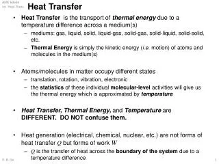
Heat Transfer Types of Heat Exchangers
1- Double Pipe Heat Exchangers W,Cp,T2 OD Hair pin ID w,cp,t1 Return bend DJ Q=w cp(t2-t1)=W Cp (T1-T2)=UoAotm w= w,cp,t2 W= - l W,Cp,T1 Ao=
Advantages of Double Pipe Heat Exchangers: • Simplest type of heat exchangers • Can be easily assembled • Relatively low cost/ft2 • Small sizes results in high Re and consequently high h • Disadvantages of Double Pipe Heat Exchangers: • Leakages are very common • Requires a lot of time in dismantling and cleaning • Small surface area of heat transfer/pipe • Space requirements are large • Double pipe heat exchangers should be considered first in design. The heat transfer surface should not exceed 200 ft2. • If several double pipes are required, their weight increases and thus the shell and tube heat exchangers is better.
2- Shell and Tube Heat Exchangers W,Cp,T1 • Non-baffled Heat Exchangers w,cp,t1 w,cp,t2 l Q = w cp(t2-t1) = W Cp (T1-T2) = UoAotm IDs W,Cp,T2 w= Nt W= - di Ao= do
Baffled Heat Exchangers 1 - 1 Heat Exchanger W,Cp,T1 w,cp,t2 w,cp,t1 Q = w cp(t2-t1) = W Cp (T1-T2) = UoAotm w= B W,Cp,T2 c W= IDs Ao=
Baffled Heat Exchangers m - n Heat Exchanger 1 - 2 Heat Exchanger W,Cp,T1 Tube passes Shell passes w,cp,t1 w,cp,t2 Q = w cp(t2-t1) = W Cp (T1-T2) = UoAotm w= B W,Cp,T2 c W= IDs Ao=
Pt: Pitch: the distance between the centers of two adjacent tubes Triangular Pitch c: Clearence: the distance between the tangents of two adjacent tubes c=Pt-do c Pt • Advantages of triangular Pitch layout: • More compact for the same shell size • More heat transfer area, thus more heat transfer • Less flow area of the shell increases its heat transfer coefficient • Disadvantages of triangular Pitch layout: • When the outer fluid causes fouling, they are difficult to clean due to their narrow interspaces • Offers high shell side pressure drop
Pt: Pitch: the distance between the centers of two adjacent tubes Square Pitch c: Clearence: the distance between the tangents of two adjacent tubes c=Pt-do c Pt • Advantages of Square Pitch layout: • Shell side pressure drop is comparatively small • Outer surface of the tubes is more accessible for cleaning with tools • Used for highly viscous or fouling shell side fluids • Disadvantages of Square Pitch layout: • Less number of tubes and thus less heat transfer area Usually, triangular pitch is preferable unless the shell side fluid is viscous or fouling
Baffles Used to increase the residence time of the shell side fluid and increase its turbulence and hence its heat transfer coefficient. B B=Baffle Spacing= the distance between two adjacent baffles The closer the baffle spacing, the smaller available flow area and consequently high shell Re and consequently high ho. Bmin<B<Bmax <B<or
2 - 4 Heat Exchanger W,Cp,T1 w,cp,t1 w,cp,t2 W,Cp,T2 Ao=
3 - 6 Heat Exchanger W,Cp,T1 w,cp,t1 w,cp,t2 W,Cp,T2 Ao=
Routing of the fluids High pressure fluids, more fouling or more corrosive fluids are routed in the tubes. More viscous fluids or low flow rate fluids (low Re) are routed in the shell.. To avoid excessive shell side pressure drop, baffles might have to be omitted in the case of highly viscous fluids. Larger flow rate stream is routed in the larger cross sectional area, so as to bring both fluid mass velocities close to one another. Cooling water or heating steam should be routed in the tubes unless the fluid being cooled or heated is under comparatively high pressure or if it is highly fouling.
Reverse Flow It is clear from the above figures that the flow of fluids in shell and tube heat exchangers are neither pure parallel nor counter flow. This flow is called reverse flow. To obtain high velocities and corresponding high heat transfer coefficients, either or both fluids must reverse directions one or more times while flowing through the exchanger. This results in a combination of counter and parallel flow. • For both reverse and cross flow exchangers, (mean temperature difference) cannot be taken as the Logarithmic Mean Temperature Difference of either parallel or counter flow only, since it is a contribution of both.
In this case, is obtained by multiplying LMTD of a counter current flow (double pipe arrangement) by a temperature difference correction factor (Ft)… • Thus Fourier’s Law takes the form: Q = UoAotm Q = UoAo Ft LMTD • The factor Ft depends on factors R and S • R=heat capacity ratio= = = T1 T2 t2 t1 • S=heating effectiveness= = Countercurrent Flow