Download
1 / 12
120 likes | 236 Views
Short Pulse Reading Concept. An initial voltage (V+,V-) can be setup by the sensing stage for the S.A. After the S.A is enabled, all initial points in the blue region above MSL will be latched as “1”, all those in the red region below MSL will be latched as “0”.

E N D
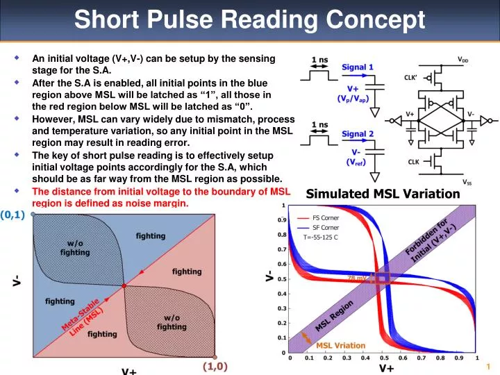
Short Pulse Reading Concept • An initial voltage (V+,V-) can be setup by the sensing stage for the S.A. • After the S.A is enabled, all initial points in the blue region above MSL will be latched as “1”, all those in the red region below MSL will be latched as “0”. • However, MSL can vary widely due to mismatch, process and temperature variation, so any initial point in the MSLregion may result in reading error. • The key of short pulse reading is to effectively setup initial voltage points accordingly for the S.A, which should be as far way from the MSL region as possible. • The distance from initial voltage to the boundary of MSLregion is defined as noise margin. Simulated MSL Variation
Direct sensing • Need to add capacitance to the input nodes of dynamic latch. Visualization of Sensing Stage
TMR v.s. RM • Rp = 2.9kΩ, VDD=1V • Increasing TMR can increase NM very effectively. For practical TMR the NM is very small. Vap Vap Vp Vp
Rpv.s. RM • TMR = 110%, VDD=1V • Only increasing Rp won’t help NM, since both Ip and Iap are affected.
Sizing v.s. RM • Rp = 2.9kΩ, TMR = 110%, VDD=1V • Purely increase the read current (e.g. by sizing the mirror transistor), won’t help RM.
Differential Sensing • Need to minimize the capacitance to the input nodes of dynamic latch. • The longer the sensing state is, the better. Visualization of Sensing Stage
Reverse Sensing • Need to minimize the capacitance to the input nodes of dynamic latch. • The longer the sensing state is, the better. Visualization of Sensing Stage
Differential Sensing NM • Need at least 2.5 ns to have worst case NM>0 Vap Vap Vp Vp
Reverse Sensing NM • NM is not symmetric, need to be optimized • Need at least 2 ns to have worst case NM>0 Vap Vap Vp Vp
Differential Sensing Improves NM Direct Sensing Differential Sensing Visualization of Sensing Stage Simulated NM for the same setting
Current Work • Optimizing and getting data from differential sensing. • Will try dual differential sensing, which should work even better.