Download
1 / 22
281 likes | 491 Views
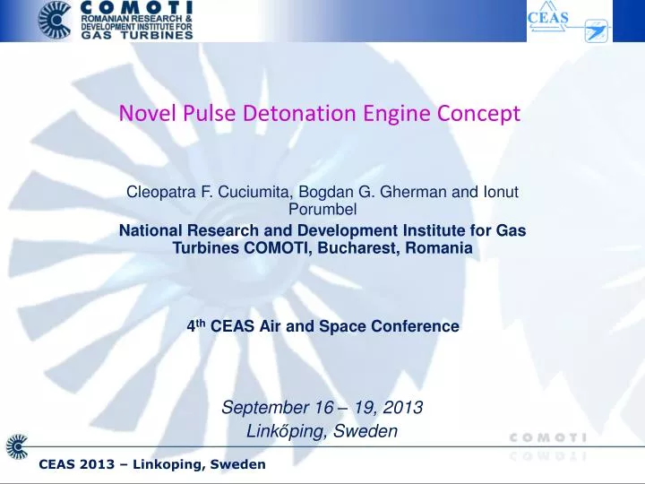
Cleopatra F. Cuciumita, Bogdan G. Gherman and Ionut Porumbel National Research and Development Institute for Gas Turbines COMOTI, Bucharest, Romania. Novel Pulse Detonation Engine Concept. 4 th CEAS Air and Space Conference. September 16 – 19, 2013 Link ő ping, Sweden.

E N D
Cleopatra F. Cuciumita,Bogdan G. Gherman and Ionut Porumbel National Research and Development Institute for Gas Turbines COMOTI, Bucharest, Romania Novel Pulse Detonation Engine Concept 4th CEAS Air and Space Conference September 16 – 19, 2013 Linkőping, Sweden CEAS 2013 – Linkoping, Sweden
Summary Overview Concept Description Fuel system diagram Ignition System Pulsed Detonation Combustors Compressor State of the Art Existing Constructive Solutions Expected Progress Project Objectives CEAS 2013 – Linkoping, Sweden
Overview • Ongoing FP 7 project breakthrough propulsion system technology a step change in air transportation • Radically new approach propulsion power reduce weight, complexity, and cost • Significant reduction of overall fuel consumption and total amount of pollutants emission • Partners: • Romanian Research and Development Institute for Gas Turbines COMOTI – Romania • Lund University – Sweden • Von Karman Institute for Fluid Mechanics – Belgium • Institute for Applied Physics – Moldova CEAS 2013 – Linkoping, Sweden
Concept Description (1) • Main idea: replacement of gas turbine by simpler system • Advantages: • Reduction in engine weight; • Removal of cycle maximum temperature limitation • Reduction of engine complexity: more reliability, lower costs, shorter manufacturing time • Reduction of engine size, particularly length • Operating principle: • Multiple rotating pulsed detonating combustors • Tangential exhaust of combustor flue gases to rotate entire combustor assembly; • Upstream compressor connected to same shaft providing high pressure to combustor CEAS 2013 – Linkoping, Sweden
Concept Description (2) • Remaining energy used to power aircraft, by: • Propeller (turboprop), • Re-axialization of flow • exhaust nozzle (turbojet) • Controlled direction of combustor exhaust • tangential velocity component drives compressor and rotating combustor assembly • axial component provides thrust by means of exhaust nozzle The engine diagram. Exhaust nozzle removed for clarity CEAS 2013 – Linkoping, Sweden
Fuel system diagram (1) • Fuel enters through channel 4 into stuffing box 11; • From here, enters rotor through circular channel 14; • Enters combustors through electronically controlled injectors through channels 6 and pipes 7 • Pressure signal transmitted through circular channel 8 to pressure transducer 10 that controls injectors CEAS 2013 – Linkoping, Sweden
Fuel system diagram (2) • Sealing of circular fuel channel and pressure channel ensured by stuffing box 11, placed between bearing casing 1 and rotor; • Stuffing box guided by slide bars preventing its rotation with respect to casing 1, while allowing axial movement; • Sealing pressure force provided by two conical springs by means of graphite rings 13 CEAS 2013 – Linkoping, Sweden
Fuel system diagram (2) • Sealing of circular fuel channel and pressure channel ensured by stuffing box 11, placed between bearing casing 1 and rotor; • Stuffing box guided by slide bars preventing its rotation with respect to casing 1, while allowing axial movement; • Sealing pressure force provided by two conical springs by means of graphite rings 13 • Induction coil mounted • on the rotor above • exit of channels; • Coil, as well as the • fuel injectors, • controlled by means of • mobile brush contacts Ignition system CEAS 2013 – Linkoping, Sweden
Pulsed Detonation Combustors (1) • Constant volume combustor operating under oscillatory conditions; • Significantly more efficient than constant pressure Brayton cycle • Speed of the burning process in detonation wave several orders of magnitude higher thermal efficiency further increases • Thermodynamic efficiencies: • 27% - Brayton cycle, • 47% - Humphrey cycle, • 49% - detonation cycle CEAS 2013 – Linkoping, Sweden
Compressor CEAS 2013 – Linkoping, Sweden
State of the Art (1) • Detonation process studied intensely in the last century; • First observed in gaseous fuels by Bertolet in 1881 • Later, Chapman and Jouguet discovered that detonation products propagate at sonic speed relative to the detonation wave. • One of the first detonation theories was the one-dimensional, detonation wave propagation theory of Chapman – Jouguet in 1905 - 1906 • Interest increased significantly with the first steps towards supersonic flight, in the mid-XX century • Various thermodynamic cycles aiming at modeling the detonation powered engine were developed: Humphrey cycle, ZDN (Zeldovich–von Neumann–Doring) cycle Fickett-Jacobs cycle CEAS 2013 – Linkoping, Sweden
State of the Art (2) • During the space race, in the ’70, new types of detonation based thrusters were studied • Over the last decade, the number of theoretical, experimental and numerical studies increased significantly • The practical application of detonation waves in propulsion system dates back to the 1940s but the complexity of the problem delayed the first successful demonstrator flight to as late as 2008 (DARPA's Blackswift). • The demonstration flight was, however, at low speed, and the project was soon cancelled. • During this time, a significant number of constructive solutions and approaches has been proposed, however none completely successful, only as far as prototypes. CEAS 2013 – Linkoping, Sweden
Existing Constructive Solutions CEAS 2013 – Linkoping, Sweden
Existing Constructive Solutions CEAS 2013 – Linkoping, Sweden
Expected progress (1) CEAS 2013 – Linkoping, Sweden
Expected progress (2) CEAS 2013 – Linkoping, Sweden
Expected progress (3) CEAS 2013 – Linkoping, Sweden
Expected progress (4) CEAS 2013 – Linkoping, Sweden
Expected progress (3) CEAS 2013 – Linkoping, Sweden
Project Objectives (1) • Given the complexity of the task, and the limited resources, the its scope is limited and does not try to tackle all the problems raised by the new engine concept. • Instead, the main goal of the project is to prove the functionality and feasibility of the concept, opening the road towards developing a mature technology over the next 50 years. • The most important result expected from the proposed project is to demonstrate, both numerically and experimentally, that the power provided by the rotating PDCs can provide the energy to accelerate the compressor to the speed required for its design performance, with sufficient excess energy to power up the aircraft. • A second achievement is expected to be the practical realization of a high frequency, self supporting ignition PDC. CEAS 2013 – Linkoping, Sweden
Project Objectives (2) • Combustor inlet will be valve free, and the solution selected to control the inlet must be proven to prevent the detonation wave to propagate upstream. A high frequency PDC is expected to be compact, both in diameter and in length, allowing significant reduction in engine dimensions and weight. • The constant volume cycle is of higher efficiency than the classical Brayton cycle. Due to the elimination of the classical engine turbine, the maximum temperature limitation will be removed, thus allowing an overall increase in the engine performance and efficiency. The project aims at demonstrating the increase in theoretical cycle efficiency. • Finally, the project will provide an integrated solution for the proposed concept, validated through numerical simulation, and laying the foundation for building a demonstrator engine concept in the future. CEAS 2013 – Linkoping, Sweden
Thank you for your attention! cleopatra.cuciumita@comoti.ro www.comoti.ro CEAS 2013 – Linkoping, Sweden