Download
1 / 1
10 likes | 172 Views
Power. Performance. V DDH V DDM V DDL. V DDH. High V T. V SUBVT. +. +. +. +. +. ModelSim Output . Processor Model. Sub-threshold PDVS data path. Single-V DD data path. V DDH . Test benches (Synthesizable VHDL ). e.g. Multi-V DD data path. VHDL. PDVS data path.

E N D
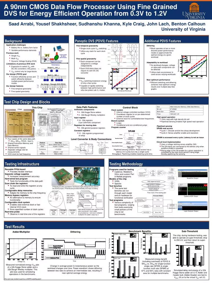
Power Performance VDDH VDDM VDDL VDDH High VT VSUBVT + + + + + ModelSim Output Processor Model Sub-threshold PDVS data path Single-VDD data path VDDH Test benches (Synthesizable VHDL) e.g. Multi-VDD data path VHDL PDVS data path VDDH VDDM VDDL x4 Register Bank Crossbar General Purpose e.g. Cadence ADE Output x8 Functional Verification & Measurement Spectre Stimulus Generation 32b + Coefficients x15 VDDH VDDM VDDL 32b x4 Silicon HW Xilinx FPGA 32 Control * Lvl. Conv. Logic Analyzer Output 160 Unified testing diagram 32kb Data Memory 40 kb Instruction Memory 4.3mm VDDH VDDM VSUBVT VCO & Inst Block Inst Memory Data Memory Headers for the multiplier Multiplier Virtual VDD 3.3mm PDVS MVDD Sub VT SVDD Headers for the adder Adder A 90nm CMOS Data Flow Processor Using Fine Grained DVS for Energy Efficient Operation from 0.3V to 1.2V SaadArrabi, Yousef Shakhsheer, Sudhanshu Khanna, Kyle Craig, John Lach, Benton Calhoun University of Virginia Background Panoptic DVS (PDVS) Features Additional PDVS Features • Application challenges • Battery life vs. battery form factor • Variable performance demands • Previous work • Single-VDD • Multi-VDD • Dynamic Voltage Scaling (DVS) • Limitations of previous DVS work • Expensive to switch VDD with DC-DC converters (10s µsecs) • VDD control only for large blocks • Our design (PDVS) goal • Function efficiently across and switch efficiently between multiple power-performance modes • Our design features • Fine temporal granularity • Fine spatial granularity • Dithering • Block operates at two or more discrete power-performance modes to approximate the optimal energy at a given workload • Adaptability to workload • As workload changes, voltage on data-path components can be dithered • Utilize slack as processor is used across varying workloads • Near optimum performance • Efficient switching and dithering achieves near-optimum energy results over multiple data flow graphs • Fine temporal granularity • Single clock cycle VDD-switching • Utilize any slack for each clock cycle • Fine spatial granularity • Each component can be assigned to a voltage independently • Each DVS block does not require its own DC-DC converter • Efficiency • VDD-switching breakeven energy of only a few cycles • Capable of rapidly switching between high performance and ultra-low power sub-VT modes Normalized Energy Single-VDD (SVDD) Multi-VDD (MVDD) Normalized Energy Normalized Workload Lower power for same performance Our design – Panoptic DVS (PDVS) Higher performance for slightly more power Normalized Workload Test Chip Design and Blocks Data Path Features This Chip Control Block • Arithmetic components • 4 - 32b Kogge Stone adders • 4 - 32b Baugh Wooley multipliers • Input register • 16 - 32b registers2 per arithmetic component • Registers for moving data • 8 - 32b general purpose registers • Constant registers • 15 - 32b registers programmedat setup • Clock system • Internal voltage controlled oscillator (VCO) • Countdown register to run pre-determined number of clock cycles • External clock for controllable/slow frequencies • Branch system • Loops • Conditional and non-conditional jumps • Program counter High speed operation • 1GHz read with high density bit-cell • Pipelined Sensing enables high speed read operation • Pipelined sensing • SRAM read access • Cycle 1: Decode and bit-line droop development • Cycle 2: Sense amplifier enable and resolution • SRAM is accessed every cycle; Latency is not an issue • Circuit level implementation • Uses a voltage latching sense amplifier (SA) • The SA inputs are connected to the bitlines only when wordline enable is asserted • Rising edge of the SA enable for a given operation is controlled by the next clock period’s rising edge, thereby pipelining the sensing SRAM Clock Read # 1 Droop Dev Read # 2 Droop Dev Level Converter & Body Connections • Four copies of the same data path • SVDD, MVDD, PDVS, Sub-VT • Shared Instruction Memory and Data Memory • Shared control signals • Separate voltage rails for measurements • VCO clock for fast frequency Wordline Enable Read # 1 SA Strobe Read # 2 SA Strobe Sense Amplifier Enable Sense Amplifier Output Data # 1 used Data # 1 valid at SRAM output Pipelined sensing scheme: Read access has a latency of 2 cycles but only a single cycle throughput. Pipelining enables lowering cycle time. Testing Methodology Testing Infrastructure • Reusable FPGA board • Providesflexible interface • Separate voltage supplies • Increases measurement accuracy • Hard-wired test program • Tests the functionality of the data path • Scan chain the registers • To read and write the registers at any cycle • Configurable delay memories • Adapts the memory to the chip frequency • Memory bypass registers • An alternative to memory to ensure functionality • Configurable clock system • Enables slow external clock or fast internal VCO clock • Runs specified number of clock cycles • Real-time probe • Observe in real-time one of the registers • Programs used for testing • Cadence, Modelsim, Xilinx and custom Perl & Matlab programs • Models of the chip • VHDL • Spectre • Test benches • The same test benches are run through each model and on hardware for functional verification • Test programs • Various complexity of test programs, ranging from tests exercising small portions of the chip to full benchmarks FPGA Board (left) and Mother Test Board (right) designed and used for the PDVS project. FPGA Board provided flexibility and ease of testing. Flow chart of the testing plan Scan chain was used to read and write to all the registers on chip Hard-wired program was used as a fail-safe mechanism. Each adder accumulates by 1 and each multiplier multiplies the adder output by 3. Test Results Benchmark Benefits Sub-Threshold Adder/Multiplier Dithering SFSR (100% rate) 67% rate The chip, during hardware testing, was able to operate at super-threshold, drop to 250 mV, and then return to super-threshold. Energy Savings Energy Savings Time Normalized Energy 50% rate Measured energy benefit (including overhead) of PDVS & MVDD vs. SVDD for single function single rate (SFSR) & single function multi rate (SFMR) at 67% and 50% rates with constant area for multiple benchmarks. Time Voltage (V) Measured normalized energy-VDD plot of a 32b Kogge Stone adder and a 32b Baugh Wooley multiplier. This plot was used for scheduling operations in the benchmarks. Change in average power & instantaneous power as the workload changes over time. Power waveform shows dithering between two rates to achieve an intermediate rate, resulting in near optimal average energy. Energy Savings Simulated delay and energy of a 32b Kogge Stone adder at 0.3 V. Adder and header bulk (Adder,Header) are tied to VDDH (H) or to the virtual VDD rail (V). This work was funded in part by a DARPAseedling grant