Download
1 / 29
300 likes | 576 Views
PROGRAMMABLE LOGICAL CONTROLLER (PLC) PRESENTED BY:- Mrs. Bindu Thakral And Jaidev Singh . Index. Introduction PLC Basics PLC and Controls History Advantages of PLCs PLC Operation Comparison to Relay Logic Applications Conclusion. Introduction.

E N D
PROGRAMMABLE LOGICAL CONTROLLER (PLC) PRESENTED BY:- Mrs. Bindu Thakral And Jaidev Singh
Index • Introduction • PLC Basics • PLC and Controls History • Advantages of PLCs • PLC Operation • Comparison to Relay Logic • Applications • Conclusion
Introduction • Programmable Logic Control, or PLC as it is universally called, is the ‘work horse’ of industrial automation. • A PLC is used to control, time and regulate the sequence. • Many production processes are controlled using PLCs like – metal machining sequences, product assembly lines and batch chemical processes.
PLC Basics • Programmable Logic Controllers (PLCs), also referred to as programmable controllers, are in the computer family. They are used in commercial and industrial applications
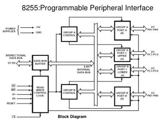
Basic PLC Operation • PLCs consist of input modules or points, a Central Processing Unit (CPU), and output modules or points.
Basic PLC Operation (cont..) • Pushbuttons (sensors), in this simple example, connected to PLC inputs, can be used to start and stop a motor connected to a PLC through a motor starter (actuator).
PLC and Controls History • Large amount of work required connecting wires • Difficulty with changes or replacements • Difficulty in finding errors; requiringskillful/experienced work force • When a problem occurs, hold-up time is indefinite, usually long • Too many moving parts
Advantages of PLCs • Number of wires reduced by approximately 80% • Fast and easy error detection. • No change in wiring to change program • Needs fewer spare parts • Cheaper when large number of I/O instruments are needed • Less moving parts • Compact • Cost effective for installation/maintenance
Components • CPU • Memory Areas • Circuits to input oroutput data • Basically, a big box of math
Specific Components •Input Relays (contacts) •Output Relays (coils) •Data Storage •Internal Utility Relays •Counters •Timers
PLC Operation • Continually scans ladder diagram • Consists of 3 important steps
Ladder Logic •Definition •Comparison to RelayLogic
Definition • One form of drawing electrical logic schematics • Very popular for PLCs • Originally invented for use with relays
Comparison to Relay Logic • First used for technicians,electricians &engineers • Still first choice for most technicians, electricians, etc.
•“Jog” function added to previous relay circuit •1 component added •3 wires added
•Two status indicators added •6 additional wires
Programming • Basics – NO/NC Contacts/Coils • AND & OR Gates • Timers and Counters • Building a PLC Ladder LogicProgramming
Basics • NO Contact • NO Coil (Output) • NC Contact • NC Coil (Output)
Timers • Very simple concept, it times • 2 basic types, on- delay and off-delay • Still sends logic as its output
Counters • Counts number of times a lever ispulled, a button ispushed, etc. • 3 types • Up Counter • Down Counter • Up-Down Counter
Building a PLC/Ladder Logic Program • To illustrate, will start in relay logic, convert to ladder logic at end • Will need to remove/replace some components
Relay Logic converted to Ladder Logic Diagram • Much fewer hard wired components • Double Pole Pushbutton for Jog switched toSingle Pole • Instead of motor relays, PLC just checks state of motor output
Applications:- • Manufacturing Industry • Food Industry • Textile Industry • Plastics Industry • And many other……
Conclusion :- We can conclude that • A lot of wiring work have been reduced • Error detection has became fast and easy • Size has been reduced • Cost effective for installation/maintenance
THANKS Q&A