Download

1 / 145
1.65k likes | 2.37k Views
Slovak University of Technology Faculty of Material Science and Technology in Trnava. THE PROGRAMMABLE LOGIC CONTROLLER. Programmable Logic Controller (PLC). PLCs have been gaining popularity on the factory floor is because of the advantages they offer :

E N D
Slovak University of Technology Faculty of Material Science and Technology in Trnava THE PROGRAMMABLE LOGIC CONTROLLER
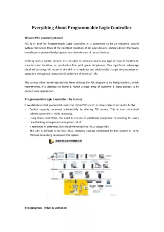
Programmable Logic Controller (PLC) • PLCs have been gaining popularity on the factory flooris because of the advantages they offer: • Cost effective for controlling complex systems. • Flexible and can be reapplied to control other systems quickly and easily. • Computational abilities allow more sophisticated control. • Trouble shooting aids make programming easier and reduce downtime. • Reliable components make these likely to operate for years before failure.
Origins of Ladder Diagram • The Ladder Diagram (LD) programming language originated from the graphical representation used to design an electrical control system • Control decisions were made using relays • After a while Relays were replaced by logic circuits • Logic gates used to make control decisions • Finally CPUs were added to take over the function of the logic circuits • I/O Devices wired to buffer transistors • Control decisions accomplished through programming • Relay Logic representation (or LD) was developed to make program creation and maintenance easier • Computer based graphical representation of wiring diagrams that was easy to understand • Reduced training and support cost
CPU Origins of Ladder Diagram
Input Instruction Output Instruction What is a Rung? • A rung of ladder diagram code can contain both input and output instructions • Input instructions perform a comparison or test and set the rung state based on the outcome • Normally left justified on the rung • Output instructions examine the rung state and execute some operation or function • In some cases output instructions can set the rung state • Normally right justified on the rung
E A D C B AND F Branches OR IF ((A OR B) AND (NOT C) AND D) THEN E=1; F=1 END_IF Series Vs Parallel Operations • Ladder Diagram input instructions perform logical AND and OR operations in and easy to understand format • If all Input Instructions in series must all be true for outputs to execute (AND) • If any input instruction in parallel is true, the outputs will execute (OR) • Paralleling outputs allows multiple operations to occur based on the same input criteria
Ladder Rung A D E Left Power Rail Right Power Rail B Branch F G H P S I J K R Ladder Logic Execution • Rungs of Ladder diagram are solved from Left to right and top to bottom • Branches within rungs are solved top left to bottom right
Non Retentive Coils • The referenced bit is reset when processor power is cycled • Coil -( )- • Sets a bit when the rung is true(1) and resets the bit when the rung is false (0) • PLC5 calls this an OTE Output Enable • Negative coil -( / )- • Sets a bit when the rung is false(0) and resets the bit when the rung is True(1) • Not commonly supported because of potential for confusion • Set (Latch) coil -(S)- • Sets a bit (1) when the rung is true and does nothing when the rung is false • Reset (Unlatch) Coil -(R)- • Resets a bit (0) when the rung is true and does nothing when the rung is false
Contacts • Normally Open Contact -| |- • Enables the rung to the right of the instruction if the rung to the left is enabled and underlining bit is set (1) • Normally Closed Contact -|/|- • Enables the rung to the right of the instruction if the rung to the left is enabled and underlining bit is reset (0) • Positive transition contact -|P|- • Enables the right side of the rung for one scan when the rung on left side of the instruction is true • Allen Bradley PLC5 uses -[ONS]- • Negative transition contact -|N|- • Enables the right side of the rung for one scan when the rung on left side of the instruction is false
Retentive Vs Non-retentive Operation • Definitions • Retentive values or instructions maintain their last state during a power cycle • Non-retentive values or instructions are reset to some default state (usually 0) after a power cycle • IEC1131 permits values to be defined as retentive • A contradiction to this is ladder diagram where 3 instructions are classified as retentive • In most PLCs only timer and coil instructions operate as non-retentive
Retentive Coils • The referenced bit is unchanged when processor power is cycled • Retentive coil -(M)- • Sets a bit when the rung is true(1) and resets the bit when the rung is false (0) • Set Retentive (Latch) coil -(SM)- • Sets a bit (1) when the rung is true and does nothing when the rung is false • PLC5 uses OTL Output Latch • Reset Retentive (Unlatch) Coil -(RM)- • Resets a bit (0) when the rung is true and does nothing when the rung is false • PLC5 uses OUT Output Unlatch
Transition Sensing Coils • Positive transition-sensing coil -(P)- • Sets the bit bit (1) when rung to the left of the instruction transitions from off(0) to on(1) • The bit is left in this state • PLC5 use OSR (One Shot Rising) • Negative transition-sensing coil -(N)- • Resets the bit (0) when rung to the left of the instruction transitions from on(1) to off(0) • The bit is left in this state • PLC5 uses OSF (One Shot Falling)
EQ ENO EN Tank1_Level IN1 100.000 Tank_max IN2 78.251 IEC Comparison Instructions in Ladder • If the rung input (EN) is enabled, the instruction performs the operation and sets the rung output (ENO) based on the comparison • Example: when EN is true, EQ (=) function compares In1 and to In2 and sets ENO • Comprehensive instruction set • EQ(=), GT (>), GE (>=), LT (<), LE (<=), NE (<>)
Pump_Tmr TON IN ENO Pump_Tmr_DN Q T#200ms PT ET 178 Pump_Tmr TON IN Q T#200ms PT ET 178 Timers in Ladder Diagram • There three timer instructions in IEC1131 • TP - Pulse timer • TON - Timer On Delay • TOF - Timer Off Delay • Time values • Time base is 1msec (1/1000 of a sec) • Values entered using duration literal format • Two possible visualizations Depending on use of EN/ENO • 1st method requires extra programming if timer done status needs to be referenced on other rungs • 2nd method sets a bit with Q which can be referenced by other logic, ENO=EN
Pulse (TP) Timing IN Q PT | 0 ET Off-Delay (TOF) Timing IN Q On-Delay (TON) Timing PT | 0 ET IN Q PT | 0 ET Timer Operation • IN = Rung input condition • Q = Comparison output results • Varies with timer types • PT = Preset Time • ET = Elapse Time
Load_Cnt CTU IN ENO Load_Cnt_DN R Q 200 PV CV 178 Load_Cnt CTU Q IN R 200 PV CV 178 Counters in Ladder Diagram • There three counter instructions in IEC1131 • CTU - Count Up Counter • CTD - Count Down Counter • CTUD - Count Up/Down Counter • All three count rung transitions • Two possible visualizations Depending on use of EN/ENO • 1st method requires extra programming if timer done status needs to be referenced on other rungs • 2nd method sets a bit with Q which can be referenced by other logic, ENO=EN
Parameters CU/CD = Count up/Down Q/QU/QD = Comparison Output R = Reset to Zero LD = Load CV with PV PV = Preset Value CV = Count Value Count Up (CTU) Counter ... ... IN Q PV | 0 CV R Count Down (CTD) Counter ... ... IN Q PV | 0 Count Up/Down (CTUD) Counter CV ... CU LD QU ... CD QD PV | 0 CV R LD Counter Operation
Jump / Label Instructions Jump to a label skips a block of code without it being scanned LBL - Named target for a jump operation JMP - Performs a jump when the rung conditions are true | Skip_Calc | |-| |-------------(JMP)--| | ... | | Skip_Calc | |---[LBL]---... CAL CAL RET RET Execution Control Elements • CALL / RETURN Instructions • Used to encapsulate logic and call it as a subroutine • Causes execution to change between functions or subroutines • CAL - Passes control to another named function • PLC5 uses JSR • RET - Exits a function and returns control back to the calling routine
Pump_Tmr TON IN ENO Pump_Tmr_DN Q TON (EN) ADD Pump_Tmr Timer Source A Tank1_In T#200ms PT ET 178 (DN) 100.000 Preset 200.000 Source B Offsetr Accum 178.251 78.251 Destination Tank_Level 178.251 + EN ENO Tank1_In Tank_Level 100.000 178.251 Offsetr 78.251 Different Instruction Presentations • The look and feel of IEC 1131-3 is somewhat different from the 1Million+ PLC’s that Allen Bradley has running in factories throughout the world • IEC places the input parameters on the outside of the instruction block vs the PLC5 where they are presented inside of the block
Extending the IEC1131-3 Instruction Set • IEC1131-3 Provides a very basic set of instructions to do simple operations (81 Ladder Diagram Instructions) • Data Type Conversion - Trunc, Int_to_Sint, Dint_to_Real, Bcd_To_Int … • Boolean Operations - Bit Test, Bit Set, One Shot, Semaphores … • Timers / Counters - Ton, Tp, Ctu, Ctd, Ctud • Simple Math - Add, Sub, Mul, Div, Mod, Move, Expt • Misc. Math - Abs, Sqrt, Ln, Log, Exp, Sin, Cos, Tan, Asin, Acos, Atan • Bit Shift - Shl, Shr, Ror, Rol • Logic - And, Or, Xor, Not • Selection - Sel, Max, Min, Limit, Mux • Compare - GT, GE, EQ, LE, LT, NE • String - Len, Left, Right, Mid, Concat, Insert, Delete, Replace, Find • Control - JMP, LBL, JSR, RET • All complex operations are left to the user or vendor to define • File Operations, PID, Diagnostic, For/Nxt Loop, Search, Sort are not in IEC1131-3 • Extensions to the instruction set are permitted so that vendors can add instructions that their customers need • All vendors have defined their own set of extensions • Rockwell Automation controllers have significantly more capabilitywith over 130 Ladder Instructions
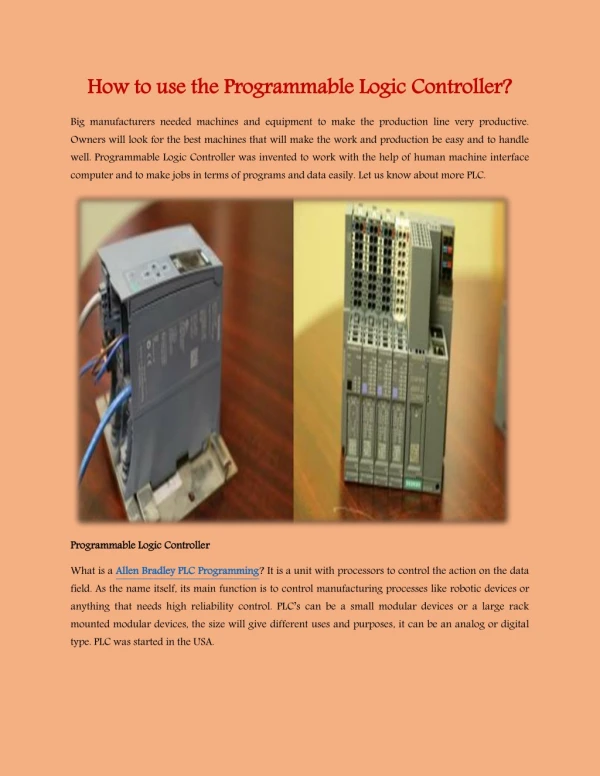
PLC HARDWARE • The most essential components PLC are: • Power Supply - 24Vdc, 120Vac, 220Vac. • CPU (Central Processing Unit) - This is a computer where ladder logic is storedand processed. • I/O (Input/Output) - A number of input/output terminals must be provided so that the PLC can monitor the process and initiate actions. • Indicator lights - These indicate the status of the PLC including power on, program running, and a fault. These are essential when diagnosing problems.
PLC HARDWARE • Typical configurations are listed below from largest to smallest: • Rack - A rack is often large (up to 18” by 30” by 10”) and can hold multiple cards. When necessary, multiple racks can be connected together. These tend to be the highest cost, but also the most flexible and easy to maintain. • Mini - These are similar in function to PLC racks, but about half the size. • Shoebox - A compact, all-in-one unit (about the size of a shoebox) that has limited expansion capabilities. Lower cost, and compactness make these ideal for small applications. • Micro - These units can be as small as a deck of cards. They tend to have fixed quantities of I/O and limited abilities, but costs will be the lowest. • Software - A software based PLC requires a computer with an interface card, but • allows the PLC to be connected to sensors and other PLCs across a network.
INPUTS FOR A PLC • Inputs for a PLC come in a few basic varieties, the simplest are AC and DC inputs. Sourcing and sinking inputs are also popular: • Sinking - When active the output allows current to flow to a common ground. This is best selected when different voltages are supplied. • Sourcing - When active, current flows from a supply, through the output deviceand to ground. This method is best used when all devices use a single supply voltage.
INPUTS FOR A PLC • In smaller PLCs the inputs are normally built in and are specified when purchasing the PLC. • For larger PLCs the inputs are purchased as modules, or cards, with 8 or 16 inputs of the same type on each card. • Inputs are normally high impedance. This means that they willuse very little current.
INPUTS FOR A PLC • There are many trade-offs when deciding which type of input cards to use. • DC voltages are usually lower, and therefore safer (i.e., 12-24V). • DC inputs are very fast, AC inputs require a longer on-time. For example, a 60Hz wave may require up to 1/60sec for reasonable recognition. • DC voltages can be connected to larger variety of electrical systems. • AC signals are more immune to noise than DC, so they are suited to long distances, and noisy (magnetic) environments. • AC power is easier and less expensive to supply to equipment. • AC signals are very common in many existing automation devices.
Output Modules • External power supplies are connected to the output card and the card will switch the power on or off for each output. Typical output voltages are listed below, androughly ordered by popularity. • 120 Vac • 24 Vdc • 12-48 Vac • 12-48 Vdc • 5Vdc (TTL) • 230 Vac
MEMORY TYPES RAM (Random Access Memory) - this memory is fast, but it will lose its contentswhen power is lost, this is known as volatile memory. Every PLC uses thismemory for the central CPU when running the PLC. ROM (Read Only Memory) - this memory is permanent and cannot be erased. It isoften used for storing the operating system for the PLC. EPROM (Erasable Programmable Read Only Memory) - this is memory that canbe programmed to behave like ROM, but it can beerased with ultraviolet lightand reprogrammed. EEPROM (Electronically Erasable Programmable Read Only Memory) - Thismemory can store programs like ROM. It can beprogrammed and erased usinga voltage, so it is becoming more popular than EPROMs.
MEMORY ADDRESSES The memory in a PLC is organized by data type as shown in Figure
PROGRAM FILES • In a PLC-5(Allen-Bradley PLCs ) the first three program files, from 0 to 2, are defined by default: • File 0 contains system information and should not be changed • File 1 is reserved for SFCs. • File 2 is available for user programs and the PLC will run the program in file 2 by default. • Other program files can be added from file 3 to 999. Typical reasons for creating other programs are for subroutines.
DATA FILES • Data files are used for storing different information types, as shown in Figure
Bit Level Addressing Memory bits are normally indicated with a forward slash followed by a bit number /n.
Integer Word Addressing • Entire words can be addressed as shown in Figure. • These values will normally be assumed to be 2s compliment, but some functions may assume otherwise
Literal Data Values • Data values do not always need to be stored in memory, they can be define literally. • Figure shows an example of two different data values
File Addressing • Sometimes we will want to refer to an array of values, as shown in Figure. • This data type is indicated by beginning the number with a pound or hash sign ’#’.
Indirect Addressing • Indirect addressing is a method for allowing a variable in a data address, as shown in Figure. • The indirect (variable) part of the address is shown between brackets ’[’ and ’]’.
Expression Data Values • Expressions allow addresses and functions to be typed in and interpreted when the program is run. • The example in Figure will get a floating point number from file 8, location 3, perform a sine transformation, and then add 1.3.
An Example of Ladder Logic Functions • The basic operation is such that while input A is true the functions will be performed.
User Bit Memory • The bit memory can be accessed with individual bits or with integer words.
BOOLEAN LOGIC DESIGN • Boolean Operations
The Basic Axioms of Boolean Algebra Duality interchange AND and OR operators, as well as all Universal, and Nullsets. The resulting equation is equivalent to the original.