Download
1 / 1
10 likes | 155 Views
Y. X. Step 1:. Temperature change is measured by infra-red detector under dynamic load.

E N D
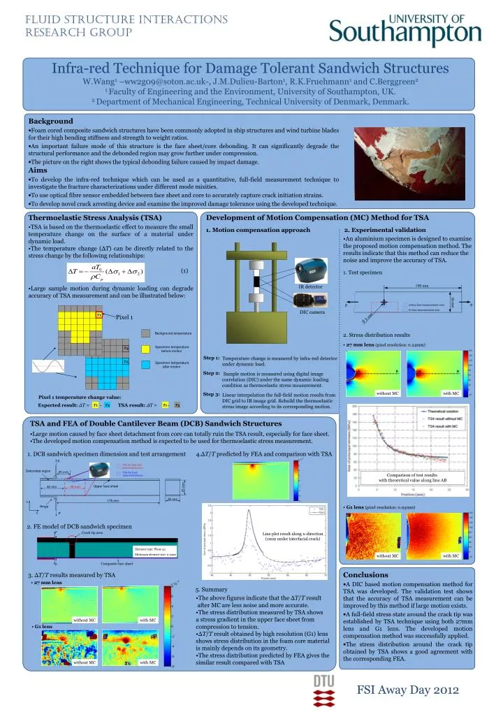
Y X Step 1: Temperature change is measured by infra-red detector under dynamic load. Sample motion is measured using digital image correlation (DIC) under the same dynamic loading condition as thermoelastic stress measurement. Linear interpolation the full-field motion results from DIC grid to IR image grid. Rebuild the thermoelastic stress image according to its corresponding motion. Step 2: Step 3: Fluid Structure Interactions Research Group Infra-red Technique for Damage Tolerant Sandwich Structures W.Wang1 –ww2g09@soton.ac.uk-, J.M.Dulieu-Barton1, R.K.Fruehmann1 and C.Berggreen2 1 Faculty of Engineering and the Environment, University of Southampton, UK. 2 Department of Mechanical Engineering, Technical University of Denmark, Denmark. • Background • Foam cored composite sandwich structures have been commonly adopted in ship structures and wind turbine blades for their high bending stiffness and strength to weight ratios. • An important failure mode of this structure is the face sheet/core debonding. It can significantly degrade the structural performance and the debonded region may grow further under compression. • The picture on the right shows the typical debonding failure caused by impact damage. • Aims • To develop the infra-red technique which can be used as a quantitative, full-field measurement technique to investigate the fracture characterizations under different mode mixities. • To use optical fibre sensor embedded between face sheet and core to accurately capture crack initiation strains. • To develop novel crack arresting device and examine the improved damage tolerance using the developed technique. Development of Motion Compensation (MC) Method for TSA • Thermoelastic Stress Analysis (TSA) • TSA is based on the thermoelastic effect to measure the small temperature change on the surface of a material under dynamic load. • The temperature change (ΔT) can be directly related to the stress change by the following relationships: 2. Experimental validation 1. Motion compensation approach • An aluminium specimen is designed to examine • the proposed motion compensation method. The • results indicate that this method can reduce the • noise and improve the accuracy of TSA. (1) 1. Test specimen IR detector • Large sample motion during dynamic loading can degrade accuracy of TSA measurement and can be illustrated below: DIC camera T1 Pixel 1 2. Stress distribution results • 27 mm lens (pixel resolution: 0.24mm) T3 T2 B B A A without MC with MC Pixel 1 temperature change value: Expected result:ΔT = - TSA result:ΔT = - T1 T3 T1 T2 TSA and FEA of Double Cantilever Beam (DCB) Sandwich Structures • Large motion caused by face sheet detachment from core can totally ruin the TSA result, especially for face sheet. • The developed motion compensation method is expected to be used for thermoelastic stress measurement. 1. DCB sandwich specimen dimension and test arrangement 4.ΔT/T predicted by FEA and comparison with TSA • G1 lens (pixel resolution: 0.03mm) 2. FE model of DCB sandwich specimen Line plot result along x-direction (1mm under interfacial crack) Element type: Plane 42 Minimum element size: 0.1mm without MC with MC • Conclusions • A DIC based motion compensation method for TSA was developed. The validation test shows that the accuracy of TSA measurement can be improved by this method if large motion exists. • A full-field stress state around the crack tip was established by TSA technique using both 27mm lens and G1 lens. The developed motion compensation method was successfully applied. • The stress distribution around the crack tip obtained by TSA shows a good agreement with the corresponding FEA. 3. ΔT/T results measured by TSA • 27 mm lens 5. Summary • The above figures indicate that the ΔT/T result • after MC are less noise and more accurate. • The stress distribution measured by TSA shows • a stress gradient in the upper face sheet from • compression to tension. • ΔT/T result obtained by high resolution (G1) lens • shows stress distribution in the foam core material • is mainly depends on its geometry. • The stress distribution predicted by FEA gives the • similar result compared with TSA without MC with MC • G1 lens without MC with MC FSI Away Day 2012