Download

1 / 26
260 likes | 300 Views
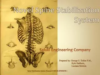
GSS 6.0 Spine System. Anatomy of the spine. Cervical vertebrae (7) Thoracic vertebrae (12) Lumbar vertebrae (5) Sacrum (5) Coccyx (4) Total 33 vertebrae. General anatomy of vertebrae. Vertebral Body: the primary area of weight bearing Vertebral arch: made up of Pedicle and Lamina

E N D
Anatomy of the spine • Cervical vertebrae (7) • Thoracic vertebrae (12) • Lumbar vertebrae (5) • Sacrum (5) • Coccyx (4) • Total 33 vertebrae
General anatomy of vertebrae • Vertebral Body: the primary area of weight bearing • Vertebral arch: made up of Pedicle and Lamina • Vertebral Foramen: containing the spinal cord • Spinous process: extends posteriorly • Transverse process: project sideways Vertebral Foramen
The motion segment • Basic functioning unit of the spine • Comprises of • Two adjacent vertebrae • Intervertebral disc • Two Facet jonits • Connecting ligaments
Indication of GSS 6.0 • Posterior spinal fusion • Including: • Fractures • Degenerative • Spinal tumor and infections
Pedicle & Reduction screws Set screw StarDrive recess A B C D • Specification • Φ4.5*30/35/40/45mm • Φ5.0*30/35/40/45/50mm • Φ5.5*30/35/40/45/50mm • Φ6.0*30/35/40/45/50mm • Φ6.5*30/35/40/45/50mm • Φ7.0*30/35/40/45/50mm Cortical thread profile design fits well in the pedicle Cancellous thread profile design fits well in the body A : Monoaxial Reduction Screw B: Monoaxial Pedicle Screw C: Polyaxial Reduction Screw D: Polyaxial Pedicle Screw The tip shape makes insertion easily
Connector & Rod Type I with block Very convenience to operate, press directly Type II with hooks Attaches directly and firmly to rod Specification: Φ4.0*60/70mm Specification:Φ3.0*50/60/70/80/90mm Type III Multi-Axial Not influenced by the processes Rod : can be cut or contour Specification:Φ3.0*50/60/70/80/90mm Specification Φ6.0*50-180mm increased every 10mm Φ6.0*200/250/300/350/400mm
Usage recommendation • GSS 6.0 is recommended to be used for Lumbar vertebrae for its strong fixation strength • GSS 5.5 is recommended to be used for Thoracic vertebrae for its low profile design • GSS 5.5 can also be used for Lumbar vertebrae of small size patients Usage Recommendation GSS5.5 GSS6.0
Patient position and incision • Place the patient in the prone position • Make a midline incision through skin down to the spinous processes of the appropriate vertebrae • Dissection is carried laterally to expose the facets and the transverse processes
Entry point of pedicle screw • The entry point of Thoracic vertebrae is the intersection of • The line of the inferior edge of the transverse process • The vertical line border of the superior articular facet • The entry point of Lumbar vertebrae is the intersection of • The line of middle of the transverse process • The vertical line border of the superior articular facet
Preparation of the pedicle cannel • Three key points need to be noticed • Instruments can not penetrate the walls of the pedicle to avoid to injure the adjacent never and vessel • The entry angle should be varied according to the anatomical feature in different vertebrates • The anterior cortex of the vertebral body should not be violated unless additional purchase if needed • The entry angle is decreased • T1&T2: 30°- 40° • T3 to T11: 20°- 25° • T12: 10° • The entry angle is increased • L1 to L3: 5°- 10° • L4: 10°- 15° • L5: 15°- 20°
Open the vertebrae • Open with the awl at the entry point • Prepare the pedicle cannel with the Lumbar Ball Probe • Make appropriate adjustments of the entry point and pedicle cannel if there is resistance during the open process. AWL LumbarBall Probe
Probe the screw channel • Use the Dual Ended Feeler to probe the screw cannel • Ensure the pedicle walls and the cortex of anterior end of the body are not violated Dual Ended Feeler
Confirm the screw angle and length • Place the Marker with the Inserter through the pedicle and into the vertebral body (the screw cannel) • Confirm the angle and depth of the pedicle cannel by the C-arm of X-ray, appropriate length of the screw can also be confirmed Inserter for Marker Marker, ball Marker, cylinder
Tap the pedicles • Select the appropriate diameter Tap (usual 0.5mm-1mm diameter smaller than the screw) to insert through the pedicle and into the body • After tapping, the feeler need to be used to ensure the pedicle walls and the cortex of the body are not violated Notes: the diameter 6.5mm of pedicle and reduction screws are most used
Screw insertion • After the pedicles prepared and the proper screw lengths determined, insert the appropriate screws (Monoaxial or Polyaxial) with the Fixed Angle Screwdriver or Multi Axial Screwdriver into the vertebrae Multi Axial Screwdriver Fixed Angle Screwdriver Notes: Each Screwdriver can be used for the pedicle & reduction screws
Rod bending and insertion • The rod template is used to determine the curvature and length of the rod needed based on the screw position • The rod may be bent using the French Bender • Place the rod into the implant heads using the Forceps Rod Holder French Bender Notes: The rod does not have to be precisely bent for attachment to the pedicle screws, especially for a Polyaxial Screw The Rod can not be bended repeatedly It is not recommended to bend the rod over 45°
Set screw insertion & Rod Placement • Place the rod into the screw head with the Forceps Rod Holder • Place the set screw to the screw head with the Dual Ended Plug Screwdriver for provisionally tighten • The Forceps can be used to facilitate the insertion Dual Ended Plug Screwdriver Forceps Rod Holder
Rod Placement(optional) • Use the Rod Pusher or Forceps Rocker to press the rod seated into the bottom of the screw head • Tighten the set screw with the StarDriver screwdriver, this is not the finally tightening Rod Pusher Forceps Rocker StarDriver screwdriver, shaft
Rod Placement(optional) • If the rod is not easily captured in the screw head or there is any dislocation of the vertebrae, the Rod Reducer with Pistol Grip can be used to fully seat the rod and simplify set screw introduction • Place the Rod Reducer over the rod, and grasp the screw head notches from above. As the Rod Reducer handle is gently squeezed, the reducer sleeve will slide down and seat the rod. Rod Reducer with Pistol Grip & De-rotation sleeve
Rod Placement (optional) • Rod Pusher or Rod Gripper can be used to adjust the rod to maintain the lordotic curve of the spine Rod Pusher, curved Rod Gripper
Compression/Distraction Distractor Forceps Compressor Forceps • Once the rod is secured in the implants, compression/distraction may be performed to place the implants in the final position • Distractor Forceps and Counter Torque can be used for distraction, and Compressor Forceps and Counter Torque for compression
Final Tightening • When all implants are securely in place, place the Hold sleeve onto the reduction screw and break the tail with the Tap Breaker • Final tightening the set screw with the Counter Torque and Torque-Limiting Driver Tap Breaker Hold Sleeve Counter Torque Torque-Limiting Driver
Connector Placement • Select the appropriate connector, place the connector on the rod with the Crosslink Holder • Adjust the position, and tighten the screw by the Screwdriver for connector Crosslink Holder Hexagonal Screwdriver
Q&A • Is a connector necessary? • It is recommended to use the connector to increase the rigidity of the whole construction • The length of the screws • The screws should extend 50-80% into the vertebral body. 40-45mm should be commonly used. • The length of the rods • Usually, 60-70mm is used for 4 screws and 80-100mm is used for 6 screws • The angle of the Reduction Screw • 30°angle of variability • The different instruments of GSS5.5 & GSS 6.0? • Multi Axial Screwdriver, Fixed Angle Screwdriver, Rod Template, Hold sleeve, Tap Breaker & Rod Reducer with Pistol Grip