Download
1 / 41
410 likes | 600 Views
BTeV Trigger. Erik Gottschalk, Fermilab (for the BTeV Trigger Group). Overview. Introduction Brief overview of the BTeV detector Level-1 trigger algorithm Trigger architecture Level-1 trigger hardware Original baseline design (digital signal processors – DSPs)

E N D
BTeV Trigger Erik Gottschalk, Fermilab (for the BTeV Trigger Group)
Overview • Introduction • Brief overview of the BTeV detector • Level-1 trigger algorithm • Trigger architecture • Level-1 trigger hardware • Original baseline design (digital signal processors – DSPs) • New baseline design (commodity hardware) • Proposed change to the new baseline design (upstream event builder & blade servers) Not covered: • Level-1 muon trigger • Level-2/3 trigger (high-level trigger – “HLT”) • Real Time Embedded Systems (RTES) Project
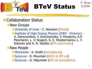
Introduction • The challenge for the BTeV trigger and data acquisition system was to reconstruct particle tracks and interaction vertices for EVERY proton-antiproton interaction in the BTeV detector, and to select interactions with B decays. • The trigger system was designed with 3 levels, referred to as Levels 1, 2, and 3:“L1” – look at every interaction and reject at least 98% of minimum bias background“L2” – use L1 computed results & perform more refined analyses for data selection“L3” – reject additional background and perform data-quality monitoringReject > 99.9% of background. Keep > 50% of B events. • The data acquisition system was designed to save all of the data in memory for as long as was necessary to analyze each interaction, and move data to L2/3 processors and archival data storage. • The key ingredients that made it possible to meet this challenge: • BTeV pixel detector with its exceptional pattern recognition capabilities • Rapid development in technology – FPGAs, processors, networking
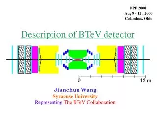
Fermi National Accelerator Laboratory Tevatron CDF BTeV at C0 D0 p p BTeV - a hadron collider B-physics experiment
RICH Dipole Magnet Muon Straws & Si Strips EM Cal BTeV Detector 30 Station Pixel Detector
sensor module 50 mm Multichip module 1 cm 400 mm 128 rows x 22 columns 5 cm pixel sensors 5 FPIX ROC’s 10 cm Readout module Sensor module Wire bonds 6 cm Bump bonds HDI flex circuit TPG substrate Silicon Pixel Detector 14,080 pixels (128 rows x 110 cols) 380,160 pixels per half-station Pixel detector half-station total of 23Million pixels in the full pixel detector
Collision Hall Counting Room to neighboring FPGA segment tracker Pixel data combiner boards Optical links FPGA segment tracker(ST) Pixel processor Pixel processor Pixel processor 12 channels @2.5Gbps 1542 channels @140Mbps from 3 pixel stations (257/half-plane) to neighboring FPGA segment tracker Debugging outputs Pixel processor 128x22 Pixel array End-of-column logic Registers & DAC’s Chip ID (13bits) Command interface Data output interface sync (1bit) Internal bond pads for chip ID LVDS drivers & IO pads FPIX2 Read-out chip Row (7bits) Column (5bits) BCO (8bits) ADC (3bits) Pixel Data Readout & 1st Part of L1 Trigger Pixel stations time stamp ordering pixel clustering xy coordinates
2.5 MHz 500 GB/s (200KB/event) 50 KHz 12.5 GB/s (250KB/event) 2.5 KHz 200 MB/s (250KB / 3.125 = 80KB/event) BTeV Trigger and Data Acquisition System L1 rate reduction: ~50x L2/3 rate reduction: ~20x
L1 Vertex Trigger Algorithm • Two stage trigger algorithm: • Segment tracking • Track/vertex finding 1) Segment tracking stage: Use pixel hits from 3 neighboring stations to find the beginning and ending segments of tracks. These segments are referred to as triplets.
Segment Tracker: Inner Triplets 1a) Segment tracking stage: phase 1 Start with inner triplets close to the interaction region. An inner triplet represents the start of a track.
Segment Tracker: Outer Triplets Track/Vertex Finding 1b) Segment finding stage: phase 2 Next, find the outer triplets close to the boundaries of the pixel detector volume. An outer triplet represents the end of a track.
Track/Vertex Finding 2a) Track finding phase: Match inner triplets with outer triplets to find complete tracks. • 2b) Vertex finding phase: • Use reconstructed tracks to locate interaction vertices • Search for tracks detached from interaction vertices
Generate Level-1 accept if “detached” tracks going into the instrumented arm of the BTeV detector with: (GeV/c)2 cm L1 Trigger Decision Execute Trigger
~0.5TB L1 Buffers Based on Commodity DRAM Output buffer (after L1 accept) PC motherboard (L1 buffer server) L1 buffer module FPGA Gigabit Ethernet (to L2/3 switch & farm) Optical Receivers (2 X 12 chan X 2.5 Gbps) L1 Buffer Memory (DDR DRAM)
Prototype L1 Buffer PCI card based L1 buffer board with commodity DRAM PC motherboard with Gigabit ethernet acting as L1 buffer server
Original Baseline: DSP-Based L1 Track/Vertex Hardware Block diagram of prototype L1 track/vertex farm hardware
33 “8GHz” Apple Xserve G5’s with dual IBM970’s (two 4GHz dual core 970’s) Front ends L1 muon Trk/Vtx node #1 Trk/Vtx node #2 Trk/Vtx node #N Ethernet switch Infiniband switch Xserve identical to track/vertex nodes New L1 Baseline using Commodity Hardware Other detectors 56 inputs at ~45 MB/s each L1 buffers Level 1 switch 33 outputs at ~76 MB/s each GL1 ITCH PTSM network Track/Vertex Farm L2/3 Switch L2/3 Farm 1 Highway
Prototype L1 Track/Vertex Hardware Infiniband switch 16 Apple Xserves Front Rear
New integrated upstream event builder architecture Current baseline architecture Proposed Upstream Event Builder Architecture described in: BTeV-doc-3342
L1 Event Building Switch L1 Farm Transformation Segment Trackers have complete events. No need for a single large switch for event building. ST ST ST ST ST ST ST ST ST TV TV TV TV TV TV TV TV TV To Global Level 1 ST: Segment Tracker TV: Track/Vertex Finder
L1 Farm Transformation ST ST ST ST ST ST ST ST ST However, we may still need a switching function to deal with TV node failures. This can be handled by smaller switches. switch switch switch TV TV TV TV TV TV TV TV TV To Global Level 1
L1 Farm Transformation ST ST ST ST ST ST ST ST ST Or, the switching function can be handled by a “Buffer Manager” as it wasdone in our DSP prototype. Which could possibly be integrated into the Segment Trackers (ST). TV TV TV TV TV TV TV TV TV To Global Level 1
Blade Server Platform In the proposed architecture we replace AppleXserves with blade servers. Intel/IBM blade server chassis Each 7U crate can hold up to 14 dual-cpu blades which are available with Intel Xeon’s (>3.0GHz) or IBM970PPC’s. 6 of these crates will fit into a standard 42U rack for a total of 168 CPU’s (on dual cpu blades) per rack.
Blade Server Platform Features front view rear view 2 network interfaces are provided on the mid-plane of the chassis: - primary/base network: each slot connects blade’s on-board gigabit- ethernet ports to a switch module in the rear - secondary hi-speed network: each slot also connects ports on the blade’s optional I/O expansion card to an optional hi-speed switch module (myrinet, infiniband, etc.) - the I/O expansion card might even be a custom card with an FPGA to implement a custom protocol.
L1 Hardware for 1 Highway with Blade Servers Complete segment tracking and track/vertex hardware for 1 highway housed in 4 blade server crates
156 MB/s out of each ST board (use 2 pairs) Module 3 Module 4 0.5 MB/s out of each L1tv node to GL1 (use 1 pair) 78 MB/s into L1tv node (use 1 pair) L1 Trigger Hardware in a Blade Server Crate From pixel pre-processor Segment tracker boards 4 MB/s to GL1 Dual CPU Track & Vertex blades
Level 1 Hardware Rack Count Complete L1 trigger hardware for one highway can fit in one 42U rack Segment finder & track/vertex hardware in 4 blade server crates Upstream event builder/pixel pre-processor Entire L1 trigger for all 8 highways in 8 42U racks
Summary The BTeV trigger evolved from an original baseline design that satisfied all BTeV trigger requirements to a new design that was easier to build, required less labor, had lower cost, and lower risk. When BTeV was canceled we were on the verge of proposing a new design to the Collaboration. This design was expected to: • reduce the cost of the trigger system • reduce the amount of space needed for the hardware • improve the design of the system architecture • improve system reliability (redundancy & fault tolerance) • improve integration of L1 & L2/3 trigger systems Ideas that we developed for the BTeV trigger are likely to be used in future high-energy physics and nuclear physics projects.
End End
FPGA segment trackers Event Building Switch: sort by crossing number track/vertex farm (~528 processors) Merge Trigger decision to Global Level 1 Level 1 Vertex Trigger 30 station pixel detector
Backup slides Backup slides
Data Rate into L1 Farm Using the triplet format proposed in BTeV-doc-1555-v2: internal triplets: 128 bits = 16 Bytes external triplets: 74 bits = 10 Bytes Then assumed 35 internal and 35 external triplets for events with <2> interactions/crossing: 35 x 26 Bytes = 910 Bytes Extrapolating linearly to 9 interactions/crossing and applying a safety factor of 2: 2 x (4.5 x 910 Bytes = 4095 Bytes) = 8190 Bytes Total rate going into L1 track/vertex farm in all 8 highways : 2.5 MHz x 8190 Bytes ~ 20 GBytes/s
Required L1 Farm Computing Power • Assume an “8.0 GHz” IBM 970: • L1 trk/vtx code (straight C code without any hardware enhancements like hash-sorter or FPGA segment-matcher) takes 379 ms/crossing on a 2.0 GHz IBM 970 (Apple G5) for minimum bias events with <6> interactions/crossing • assume following: • L1 code: 50%, RTES: 10%, spare capacity: 40% • 379 ms + 76 ms + 303 ms = 758 ms • 758 ms ÷ 4 = 190 ms on a 8.0 GHz IBM 970 • Include additional 10% processing for L1-buffer operations in each node • 190 ms + 19 ms = 209 ms • Number of “8.0 GHz” IBM 970’s needed for L1 track/vertex farm: • 209 ms/396 ns = 528 cpu’s for all 8 highways, 66 cpu’s per highway • 33 dual cpu Apple Xserve G5’s per highway
L1 Segment Tracker on a PTA Card Uses Altera APEX EPC20K1000 instead of EP20K200 on regular PTA Modified version of PCI Test Adapter card developed at Fermilab for testing hardware implementation of 3-station segment tracker (a.k.a. “Super PTA”)
Prototype L2/3 farm Prototype L2/3 farm using nodes from retired FNAL farms
Real Time Embedded Systems (RTES) • RTES: NSF ITR (Information Technology Research) funded project • Collaboration of computer scientists, physicists & engineers from: • Univ. of Illinois, Pittsburgh, Syracuse, Vanderbilt & Fermilab • Working to address problem of reliability in large-scale clusters with real time constraints • BTeV trigger provides concrete problem for RTES on which to conduct their research • and apply their solutions