Download
1 / 25
250 likes | 258 Views
André Marie AMPÈRE (1775 - 1836 ). Electric Circuits. Count Alessandro Volta (1745 - 1827). Georg Simon Ohm (1787 - 1854). Charles Augustin de Coulomb (1736 – 1806). Carbon Electrode (+). Zn Electrode (-). _ _ _. + + +. Zn + Zn +. Zn + Zn +. Sulfuric acid.

E N D
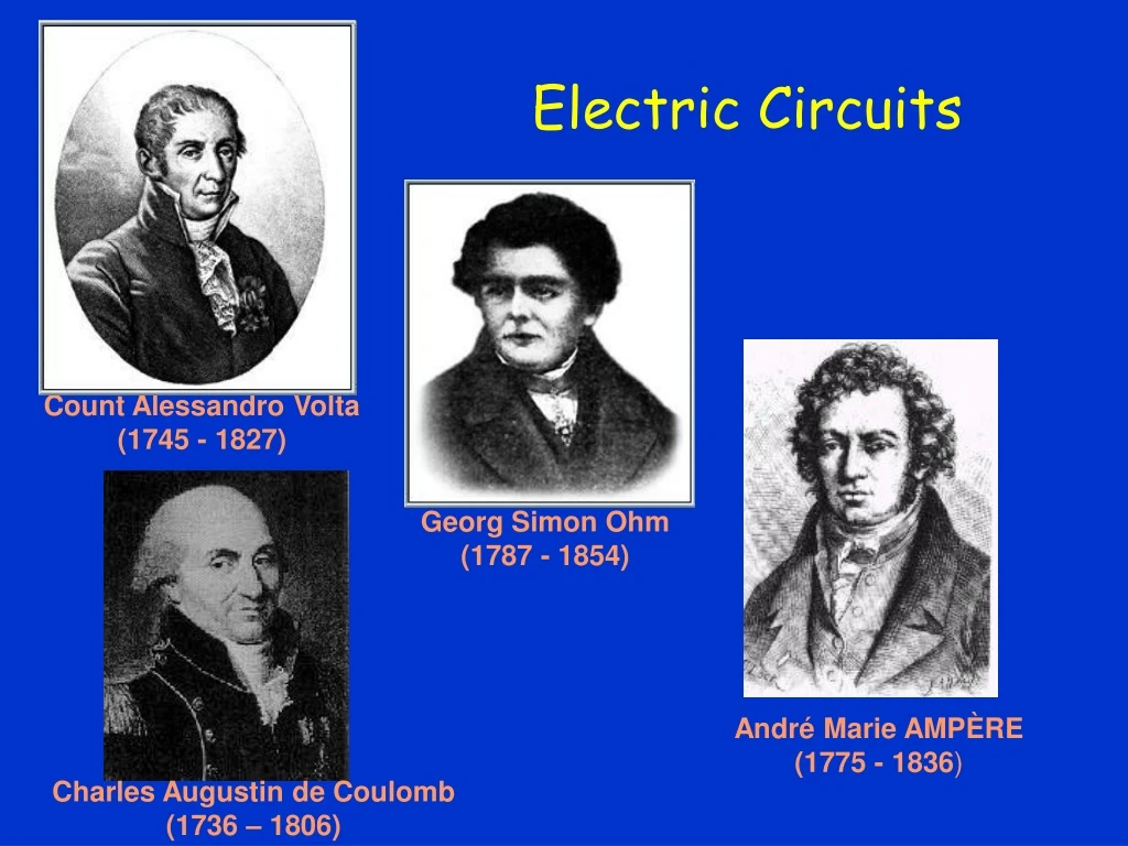
André Marie AMPÈRE (1775 - 1836) Electric Circuits Count Alessandro Volta(1745 - 1827) Georg Simon Ohm(1787 - 1854) Charles Augustin de Coulomb (1736 – 1806)
Carbon Electrode (+) Zn Electrode (-) _ _ _ + + + Zn+ Zn+ Zn+ Zn+ Sulfuric acid Simple Electric Cell wire • Two dissimilar metals or carbon rods in acid • Zn+ ions enter acid leaving terminal negative • Electrons leave carbon leaving it positive • Terminals connected to external circuit • ‘Battery’ referred to several cells originally
Electric Current Electrons flow out of the negative terminal and toward the positive terminal electric current. (We will consider conventional current – positive charges move Electric current I is defined as the rate at which charge flows past a given point per unit time. 1 C/s = 1A (ampere)
Electric Circuit • It is necessary to have a complete circuit in order for current to flow. • The symbol for a battery in a circuit diagram is: “Conventional” current direction is opposite to actual electron flow direction which is – to +. _ + Current Device 9 volts +
Ohm’s Law • For wires and other circuit devices, the current is proportional to the voltage applied to its ends: I V • The current also depends on the amount of resistance that the wire offers to the electrons for a given voltage V. We define a quantity called resistance R such that V = I R (Ohm’s Law) • The unit of resistance is the ohm which is represented by the Greek capital omega ().
Resistors Resistor Code Resistor Code Calculator Resistor • A resistor is a circuit device that has a fixed resistance. Circuit symbol Resistors obey Ohm’s law but not all circuit devices do. I I 0 V 0 V Resistor non-ohmic device
Resistivity table Resistivity • Property of bulk matter related to resistance of a sample is the resistivity(r)defined as: The resistivity varies greatly with the sort of material: e.g., for copper r ~ 10-8W-m;for glass, r ~ 10+12W-m; for semiconductors r ~ 1 W-m; for superconductors, r = 0 [see Appendix]
R I I V V slope = R How to calculate the resistance? I Include “resistivity” of material Include geometry of resistor Ohm’sLaw • Demo: • Vary applied voltage V. • Measure currentI • Does ratio remain constant?
R I I V Resistance • Resistance • Resistance is defined to be the ratio of the applied voltage to the current passing through. UNIT: OHM = W • How do we calculate it? • Recall the case of capacitance: (C=Q/V) depended on the geometry (and dielectric constant), not on QorVindividually • Similarly, for resistance • part depends on the geometry (length L and cross-sectional area A) • part depends on the “resistivity” ρ of the material • Increase the length flow of electrons impeded • Increase the cross sectional area flow facilitated • What about r?
Two cylindrical resistors are made from the same material, and they are equal in length. The first resistor has diameter d, and the second resistor has diameter 2d. 1) Compare the resistance of the two cylinders. a) R1 > R2 b) R1 = R2 c) R1 < R2 2) If the same current flows through both resistors, compare the average velocities of the electrons in the two resistors: a) v1 > v2 b) v1 = v2 c) v1 < v2
Strain Gauge • A very thin metal wire patterned as shown is bonded to some structure. • As the structure is deformed slightly, this stretches the wire (slightly). • When this happens, the resistance of the wire: (c) stays the same (b) increases (a) decreases Because the wire is slightly longer, is slightly increased. Also, because the overall volume of the wire is ~constant, increasing the length decreases the area A, which also increases the resistance. By carefully measuring the change in resistance, the strain in the structure may be determined.
Power in Electric Circuits • Electrical circuits can transmit and consume energy. • When a charge Q moves through a potential difference V, the energy transferred is QV. • Power is energy/time and thus: and thus:
Notes on Power • The formula for power applies to devices that provide power such as a battery as well as to devices that consume or dissipate power such as resistors, light bulbs and electric motors. • The formula for power can be combined with Ohm’s Law to give other versions:
Household Power • Electric companies usually bill by the kilowatt-hour (kWh.) which is the energy consumed by using 1.0 kW for one hour. • Thus a 100 W light bulb could burn for 10 hours and consume 1.0 kWh. • Electric circuits in a building are protected by a fuse or circuit breaker which shuts down the electricity in the circuit if the current exceeds a certain value. This prevents the wires from heating up when carrying too much current.
a I R1 The Voltage “drops”: b R2 a c Reffective Whenever devices are in SERIES, the current is the same through both ! This reduces the circuit to: c Hence: Resistorsin Series
e1 R I1 e2 I2 R I3 e3 R
R1 V0 V R2 By varying R2 we can controllably adjust the output voltage! Voltage Divider
Voltage Divider Two resistors are connected in series to a battery with emf E. The resistances are such that R1 = 2R2. Compare the current through R1 with the current throughR2: a) I1 > I2 b) I1 = I2 c) I1 < I2 What is the potential difference across R2? a) V2 = E b) V2 = 1/2 E c) V2 = 1/3 E
What to do? I a I1 I2 • Very generally, devices in parallel have the same voltage drop V R1 R2 • But current through R1 is not I ! Call itI1. Similarly, R2«I2. I d KVL Þ I • How is I related to I1 & I2 ? • Current is conserved! a V R I d Þ Þ Resistors in Parallel
Consider two cylindrical resistors with cross-sectional areas A1 and A2 A2 A1 V R1 R2 Put them together, side by side … to make one “fatter”one, Þ Another way… Resistivity
50W a b I2 I1 20W 80W 12V c d (a)(Va-Vd) < (Va-Vc) (b)(Va-Vd) = (Va-Vc) (c)(Va-Vd) > (Va-Vc) 2 1B • What is the relation between I1 and I2? (c)I1 > I2 (b)I1 = I2 (a)I1 < I2 Circuit Practice • Consider the circuit shown: • What is the relation between Va-Vd and Va -Vc ? 1
50W a b I2 I1 20W 80W 12V c d (a)(Va-Vd) < (Va-Vc) (b)(Va-Vd) = (Va-Vc) (c)(Va-Vd) > (Va-Vc) Circuit Practice • Consider the circuit shown: • What is the relation between Va -Vd and Va -Vc ? 1 • Do you remember that thing about potential being independent of path? • Well, that’s what’s going on here !!! • (Va-Vd) = (Va-Vc) • Point d and c are the same, electrically
50W a b I2 I1 20W 80W 12V c d (a)(Va-Vd) < (Va-Vc) (b)(Va-Vd) = (Va-Vc) (c)(Va-Vd) > (Va-Vc) (c)I1 > I2 (b)I1 = I2 (a)I1 < I2 • Note that: Vb-Vd = Vb-Vc • Therefore, Circuit Practice • Consider the circuit shown: • What is the relation between Va -Vd and Va -Vc ? 2 • What is the relation between I1 and I2?
Summary of Simple Circuits • Resistors in series: Current thru is same; Voltage drop across is IRi • Resistors in parallel: Voltage drop across is same; Current thru is V/Ri
Two identical light bulbs are represented by the resistors R2 & R3 (R2 = R3 ). The switch S is initially open. If switch S is closed, what happens to the brightness of the bulb R2? a) It increases b) It decreases c) It doesn’t change What happens to the current I, after the switch is closed ? a) Iafter = 1/2 Ibefore b) Iafter = Ibefore c) Iafter = 2 Ibefore