Download
1 / 17
220 likes | 635 Views
COMMUNICATION SYSTEM EECB353 Chapter 2 Part II AMPLITUDE MODULATION. Azlina Abdullah Dept of Electrical Engineering Universiti Tenaga Nasional. AM Voltage Distribution. Mathematically an unmodulated carrier can be described as: where v c (t) = time-varying voltage for the carrier

E N D
COMMUNICATION SYSTEM EECB353Chapter 2 Part IIAMPLITUDE MODULATION Azlina Abdullah Dept of Electrical Engineering Universiti Tenaga Nasional
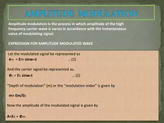
AM Voltage Distribution • Mathematically an unmodulated carrier can be described as: where vc(t) = time-varying voltage for the carrier Ec = peak carrier amplitude (volts) fc = carrier frequency (hertz) • But Vmax = Ec + Em , then the instantaneous modulated amplitude: where= amplitude of modulated wave Em = peak change in the amplitude of the envelope (volts) fm = frequency of the modulating signal (hertz)
AM Voltage Distribution Em = mEc = constant + modulating signal = unmodulated carrier Carrier Signal Upper side freq signal Lower side freq signal
AM Voltage Distribution Vam • Notes from DSBFC eqn,Vam • Amplitude of the carrier Ec is unaffected by the modulation process • Amplitude of the upper (Eusf) and lower side frequencies (Elsf )depend on both carrier amplitude, Ec and coefficient of modulation,m. Voltage Spectrum for AM DSBFC wave
Example 3 • One input to a conventional AM modulator is a 500kHz carrier with an amplitude of 20Vp. The second input is a 10kHz modulating signal that is of sufficient amplitude to cause a change in the output wave of 7.5Vp. Determine • Upper and lower side frequencies. • Modulation coefficient and percent modulation • Peak amplitude of the modulated carrier and the upper and lower side frequency voltages. • Maximum and minimum amplitudes of the envelope. • Expression for the modulated wave. • Draw the output spectrum. • Sketch the output envelope.
Example 4 • If the modulated wave has the equation, find (a) the carrier freq (b) the usf and lsf (c) the modulating signal freq (d) the peak amplitude of the carrier signal (e) the upper and lower side signal peak amplitude (f) the change In peak amplitude of the modulated wave (g) the coefficient of modulation.
AM Power Distribution • The average power dissipated in a load by unmodulated carrier is equal to the rms carrier voltage, Ec squared divided by the load resistance, R. • Mathematically, power in unmodulated carrier, Pc is:
AM Power Distribution • The upper and lower sideband powers: where mEc/2 is the peak voltage of usf and lsf. Then, • Total transmitted power in DSBFC AM envelope:
AM Power Distribution Power Spectrum for AM DSBFC wave • Note: • Carrier power in the modulated signal is the same in the unmodulated signal i.e carrier power is unaffected by the modulation process. • The total power in an AM envelope increase with modulation (i.e as m, Pt). • Major disadvantage of AM DSBFC is most of the power is wasted in the carrier. (It does not contain info, info is contained in the sidebands).
Efficiency of AM • Efficiency, E is defined as the percentage of total power that conveys information i.e it is the percentage of total transmitted power that is in the sidebands.
Example 5 • Draw the power spectrum for a given expression and determine the modulation index and efficiency. (Assume R=1Ω)
Example 6 • Determine the maximum sideband power if the carrier output is 1 kW and calculate the total maximum transmitted power.
Importance of High-percentage Modulation Table: Effective transmission at 50% versus 100% modulation • Notes • Even though the total transmitted power has only fallen from 1.5kW to 1.125kW, the effective transmission has only ¼ the strength at 50% modulation as compared to 100%. • Because of these considerations, most AM transmitter attempts to maintain between 90 and 95 percent modulation as a compromise between efficiency and the chance of drifting into overmodulation.
Example 7 • A DSBFC AM Signal with a 1kW carrier was modulated to a depth of 60%. How much power is contained in the upper sideband? Given then, but, total power
Example 8 The total power of an AM transmitter is measured to be 850W. What is the total output sideband power if it has a percent modulation of 100%? Calculate the efficiency.
Example 9 • For an AM DSBFC wave with a peak unmodulated carrier voltage Vc= 10Vp, a load resistance RL = 10, and a modulation coefficient, m = 1, determine • Powers of the carrier and the upper and lower sidebands. • Total sideband power. • Total power of the modulated wave. • Draw the power spectrum. • Repeat steps (a) to (d) for a modulation index, m = 0.5.
Example 10 A 1.5MHz carrier signal is modulated with 3.4kHz modulating signal. The modulated carrier voltage is 28Vmax and 14Vmin across a 100Ω resistive load impedance. Determine: a) Peak amplitude of the unmodulated carrier. b) Coefficient of modulation c) Carrier power. d) Sideband power e) Total power f) Upper and lower sideband frequencies. g) Bandwidth.