Download
1 / 17
210 likes | 539 Views
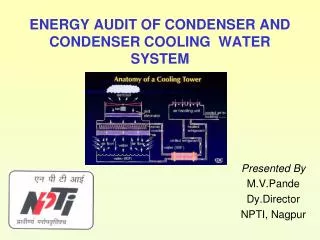
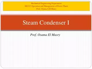
Mechanical Engineering Department ME332 Operation and Management of Power Plants Prof. Osama A El Masry. Steam Condenser II. Prof. Osama El Masry. Steam Condenser Design. Assumption while design heat exchanger

E N D
Mechanical Engineering Department ME332 Operation and Management of Power Plants Prof. Osama A El Masry Steam Condenser II Prof. Osama El Masry
Steam Condenser Design • Assumption while design heat exchanger • The heat exchanger operates under steady-state conditions [i.e., constant flow rates and fluid temperatures (at the inlet and within the exchanger) independent of time]. • Heat losses to or from the surroundings are negligible (i.e. the heat exchanger outside walls are adiabatic). • There are no thermal energy sources or sinks in the exchanger walls or fluids, such as electric heating, chemical reaction, or nuclear processes. • The temperature of each fluid is uniform over every cross section in counter flow and parallel flow exchangers. For a multipass exchanger, the foregoing statements apply to each pass depending on the basic flow arrangement of the passes; the fluid is considered mixed or unmixed between passes as specified.
5. Wall thermal resistance is distributed uniformly in the entire exchanger. 6.The phase change occurs at a constant temperature as for a single-component fluid at constant pressure; the effective specific heat cpeff for the phase-changing fluid is infinity in this case, and hence Cmax = m cpeff 00, where m is the fluid mass flow rate. 7. Longitudinal heat conduction in the fluids and in the wall is negligible. 8. The individual and overall heat transfer coefficients are constant (independent of temperature, time, and position) throughout the exchanger, including the case of phase changing fluids in assumption 6. 9. The specific heat of each fluid is constant throughout the exchanger, so that heat capacity rate on each side is treated as constant.
10. . The heat transfer surface area A is distributed uniformly on each fluid side in a single-pass or multipass exchanger. In a multipass unit, the heat transfer surface area is distributed uniformly in each pass, although different passes can have different surface areas. 11. The velocity and temperature at the entrance of the heat exchanger on each fluids side are uniform over the flow cross section. There is no gross flow misdistribution at the inlet. 12. The fluid flow rate is uniformly distributed through the exchanger on each fluid side in each pass i.e., no passage-to-passage or viscosity-induced misdistribution occurs in the exchanger core. Also, no flow stratification, flow bypassing, or flow leakages occur in any stream. The flow condition is characterized by the bulk (or mean) velocity at any cross section
Condenser Design H.T. Calculation Temperature Profile
Heat Transfer Dimensionless numbers and properties: Prandalt number Reynolds number Heat transfer co-efficients Inside boundary of tube Outside boundary of tube assume that outside heat transfer co-efficient is 1.5 times the inside heat transfer co-efficient Overall heat transfer co-efficient:
Heat Transfer • Q = UA ∆Tm • ∆Tm= The overall H.T. coefficient U can also be expressed by the emperical Equation: C1, C2 ,C3 and C4 are obtained from the tables: U= C1C2C3C4 √v
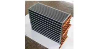
Surface area required • A=Q/ U ∆Tm • A= (πd) x l x n Water calculation • mw= Q/cp (T2 – T1) • T2 – T1=∆Ti -∆To • cpwater=4.18 kJ/kg oK
Pressure drop Pressure drop in condenser water box, m (A)one-pass, (B)two-pass
Pressure drop Pressure drop in condenser tubes m/m length of tube
Example Design a condenser that would handle 1000 ton/h of 90% quality steam at 6 kPa and 120 ton/h of 45oC drain water from FWH and 0.6 ton/h of 210 oC drains from the steam jet ejector. Fresh cooling water is available at 20 oC. Solution H.T. calculation: Select: • A two-pass condenser • Type 304 stainless steel tubing • Tubes 16 m in length, 7/8 OD, 18 BWG • TTD = 4 oC • Inlet water velocity 2m/s
Heat load Q = 1000 x 103 x (xhfg)+120 x 103(h45oC -hf) + 0.6 x 10³(h210oC -hf) =1000 x 103 x (2174.4)+120 x 103(36.9) + 0.6 x 10³(746.2) =103x (2174400+4428+447.7)=2.175 x 10⁹ kJ/h=604.16 x106 W ∆Ti= tsat-20=36.2-20=16.2 oC ∆To= 4 oC ∆Tm=(16.2-4)/ ln(16.2/4)=12.2/1.399=8.72 oC Q = UA ∆Tm(1) U= C1C2C3C4 √v (2) From tables • From tables U= 2705x 0.86x 0.58x0.58 √2=1106.7 W/m2. oC • Total surface area=62,604 m2 • For 7/8-in tubes surface area/m is 0.0698 m2 and cross-section area=3.879cm2 • A /π d = ltotal • Total length of tubes= 896,905 m
ltotal = l x n Number of tubes=56,056 tubes 28,028 tubes/pass • Water calculation: T2 – T1=∆Ti -∆To= 12.2 oC For cpwater=4.18 kJ/kg oK mw= Q/cp (T2 – T1)= 604.16 x10³/4.18x12.2 =11.8x10³kg/s=42,650 Ton/h • check using Continuaty Equation • Mass flow rate= ρ x v x A x n/2=10.87 x103kg/s=39,132 Ton/h
Pressure drop Pressure drop in water box= 0.833 m=0.0817 bar Pressure drop in tubes=0.3 m/m length=0.0294 bar Allow for 0.05 m thick tube sheet Each pass will have a length of 16.1 m Total pressure drop= 0.0294 x 2 x 16.1=0.945 bar Total pressure drop in the condenser= 0.945+0.0817=1.029 bar • Power= m ∆P/ ρ=1214.63 kW