Download
1 / 51
720 likes | 1.2k Views
Analog Modulation . (Bilingual Teaching ). Chapter 5 Analog Modulation. INTRODUCTION TO MODULATION 5.1 AMPLITUDE MODULATlON 5.2 NOISE IN AM SYSYEMS 5.3 ANGLE MODULATlON 5.4 NOISE IN FM RECIVERS 5.5 MULTIPLEXING 5.6 FM-RADIO AND TV BOADCASTING. THE KEY OF THIS CHAPTER.

E N D
Analog Modulation (Bilingual Teaching )
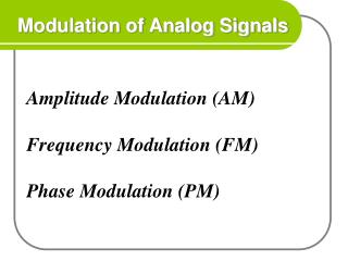
Chapter 5 Analog Modulation • INTRODUCTION TO MODULATION • 5.1 AMPLITUDE MODULATlON • 5.2 NOISE IN AM SYSYEMS • 5.3 ANGLE MODULATlON • 5.4 NOISE IN FM RECIVERS • 5.5 MULTIPLEXING • 5.6 FM-RADIO AND TV BOADCASTING
THE KEY OF THIS CHAPTER • Characteristic of theConventional, Double-Sideband Suppressed-Carrier, Single-SidebandandVestigial-Sideband Amplitude modulation • Noise performance of different AM systems
THE KEY OF THIS CHAPTER • The relationship between FM and PM • Implementation of ANGLE modulators and demodulators • Noise in FM receivers
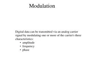
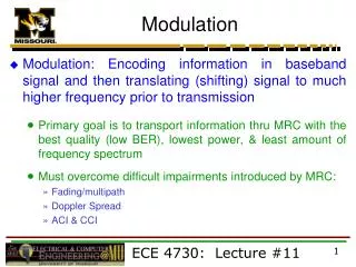
INTRODUCTION TO MODULATION • Why Modulation is Used? Using carrier to shape and shift the frequency spectrum enable modulation by which several advantages are obtained: • different radio bandscan be used for communications • wirelesscommunications (smaller antennas ) • multiplexing techniques become applicable
INTRODUCTION TO MODULATION • message signal: The analog signal to be transmitted is denote by m(t): • A lowpass signal of bandwidth W , • The power content of this signal is: • m(t) is transmitted through the channel by impressing it on a carrier signal:
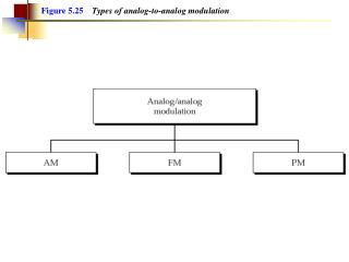
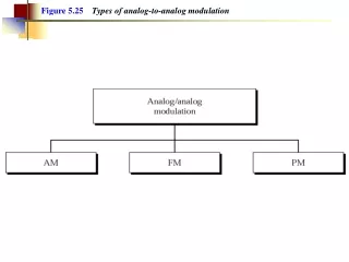
AMPLITUDE MODULATlON • Several different ways of amplitude modulating the carrier signal by m(t) : • (a) conventional double-sideband AM, • (b) double sideband suppressed-carrier AM, • (c) single-sideband AM, • (d) vestigial-sideband AM. each way results in different spectral characteristics for the transmitted signal.
Conventional Amplitude Modulation AM modulation model A conventional AM signal in the time domain
Conventional Amplitude Modulation • m(t) is constrained to satisfy : • If the AM signal is overmodulated • Spectrum of the AM Signal F +F
Example 5.1.1 • Modulating signal m(t) is a sinusoid : Determine the AM signal, its upper and lower sidebands, and its spectrum. • Solution:the AM signal is expressed as • modulation index:
so that The lower sideband component is: The upper sideband component is :
The spectrum of the AM signal The power of carrier component is Ac2/ 2 The power of two sideband is Ac2β/ 4
Conventional Amplitude Modulation • The power content of the AM signal is :
Conventional Amplitude Modulation • Since the envelope is slowly varying, the positive and the negative halves of each cycle have almost the same amplitude. integral of is almost zero .
Conventional Amplitude Modulation • So • Note that the second component is much smaller than the first component ( ). This shows that the conventional AM systems are far less power efficient than the DSB-SC systems described in next subsection.
Conventional Amplitude Modulation rectify the received signal lowpass filter • Demodulation of Conventional AM Signals DC component output of the envelope detector envelope detector gain factor due to the signal demodulator
Double-Sideband Suppressed-Carrier AM • DSB-SC AM signal is obtained by
Double-Sideband Suppressed-Carrier AM An example of message, carrier,and DSB-SC modulated signals.
Double-Sideband Suppressed-Carrier AM • Spectrum of the DSB-SC AM Signal. • The bandwidth occupancy of the amplitude-modulated signal is 2W • the channel bandwidth required Bc=2W. • And it does not contain • a carrier component For this reason, u(t) is called a suppressed-carrier signal.
Double-Sideband Suppressed-Carrier AM • Power Content of DSB-SC Signals. Pm indicates the power in the message signal m(t)
Double-Sideband Suppressed-Carrier AM • Example 5.1.2 The modulating signal DSB-SC signal and its upper and lower sidebands Solution : in the time domain
Taking the Fourier transform The lower sideband of u(t) The upper sideband of u(t)
Spectrum of u(t) lower sideband upper sideband
Modulated signal u(t) (X) Modulator LPF (low pass filter) v(t) vo(t) Accos(2pfct+f) Local oscillator Demodulation of DSB-SC AM Signals. Double-Sideband Suppressed-Carrier AM • suppose the received signal: • multiplying r(t) by a locally generated sinusoid:
Double-Sideband Suppressed-Carrier AM • Then, we pass the product signal through an ideal lowpass filter with the bandwidth W: • Then: • Note that m(t) is multiplied by:
Single-Sideband AM • A DSB-SC AM signal required a channel bandwidth of Bc=2Wfor transmission, where W is the bandwidth of the message signal. • We reduce the bandwidth of the transmitted signal to that of the baseband message signal m(t). the Hilbert transform of m(t) upper sideband lower sideband
Hilbert transform • Hilbert transform may be viewed as a linear filter with impulse response and frequency response With phase shift p/2
Single-Sideband AM Generation of a single-sideband AM signal by filtering one of the sidebands of a DSB-SCAM signal. Generation of a lower single-sideband AM signal
Example 5.1.4 • the modulating signal is a sinusoid Determine the two possible SSB-AM signals. • Solution : The Hilbert transform of m(t) is : Hence, (-) sign USSB signal (+) sign LSSB signal
Single-Sideband AM • Demodulation of SSB-AM Signals for the USSB signal : passing the signal through an ideal lowpass filter
Vestigial-Sideband AM • Sideband filter in an SSB-AM system is stringent • Can be relaxed by allowing vestige , which is a portion of the unwanted sideband
Vestigial-Sideband AM • A DSB-SC AM signal passing through a sideband filter with the frequency response H(f)
Vestigial-Sideband AM • Demodulation of the VSB signal
Vestigial-Sideband AM • The lowpass filter frequency range • VSB-filter characteristic must satisfy :
Implementation of AM Modulators and demodulatiors • Power-Law Modulation Block diagram of power-law AM modulator generate a product of the m(t) with the carrier
Switching Modulator. • passing vo(t) through a bandpass filter with the center frequency f = fc and the bandwidth 2W
Balanced Modulator. Care must be taken to select modulators with approximately identical characteristics so that the carrier component cancels out at the summing junction.
Ring Modulator. The switching of the diodes is controlledby a square wave of frequencyfc,
Demodulation of AM signals • Envelope Detector. simple lowpass filter
Demodulation of DSB-SC AM Signals • Note that m(t) is multiplied by: Requires a synchronous demodulator
Demodulation of SSB and VSB Signals VSB signal: carrier component that is transmitted along with the message SSB signal: insert a small carrier component that is transmitted along with the message
NOISE IN AM SYSYEMS • Channel and Receiver model • Channel model Additive white Gaussian noise (AWGN) communication channel . • Receiver model Ideal band-pass filter followed by an ideal demodulator
NOISE IN AM SYSYEMS • Signal-to-noise ratios • Let the power spectral density of the noise w(t) be denoted by n0/2 , n0 is the average noise power per unit bandwidth measured at the front end of the receiver • the band-pass filter having a bandwidth equal to the transmission bandwidth Bc Conventional-AM SSB DSB-SC VSB
Channel and Receiver model • The filtered noise n(t) as a narrowband noise : the quadrature noise component the in-phase noise component • The filtered signal x(t) available for demodulation is defined by