Download
1 / 21
530 likes | 1.43k Views
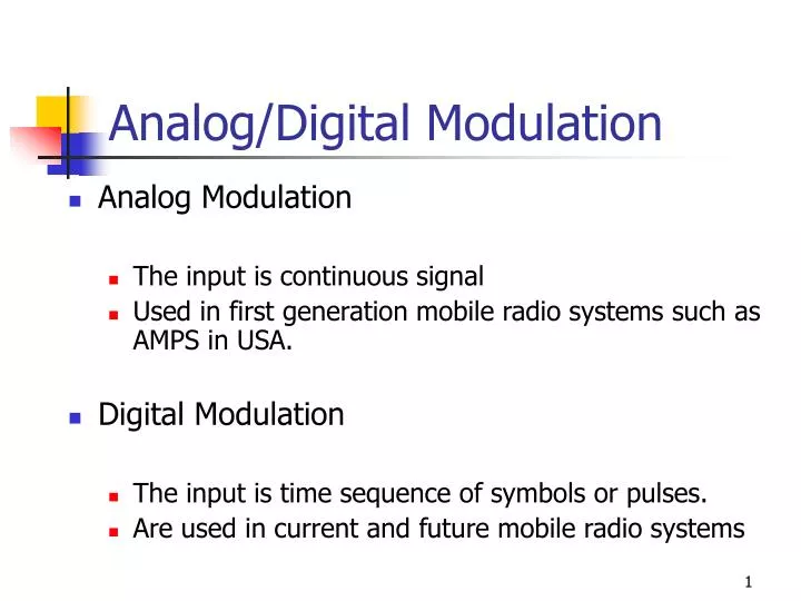
Analog/Digital Modulation. Analog Modulation The input is continuous signal Used in first generation mobile radio systems such as AMPS in USA. Digital Modulation The input is time sequence of symbols or pulses. Are used in current and future mobile radio systems. Performance Metrics.

E N D
Analog/Digital Modulation • Analog Modulation • The input is continuous signal • Used in first generation mobile radio systems such as AMPS in USA. • Digital Modulation • The input is time sequence of symbols or pulses. • Are used in current and future mobile radio systems
Performance Metrics • In analog communications we want, • Digital communication systems: • Data rate (R bps) Limited by Channel Capacity • Probability of error • Without noise, there are no bit errors • Bit Error Rate (BER): Number of bit errors that occur for a given number of bits transmitted. • What’s BER if Pe=10-6 and 107 bits are transmitted?
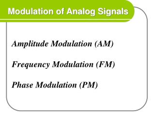
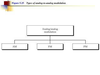
Frequency versus Amplitude Modulation • Frequency Modulation (FM) • Most popular analog modulation technique • Amplitude of the carrier signal is kept constant (constant envelope signal), the frequency of carrier is changed according to the amplitude of the modulating message signal; hence info is carried in the phase or frequency of the carrier. • Has better noise immunity: • atmospheric or impulse noise cause rapid fluctuations in the amplitude of the received signal • Performs better in multipath environment • Small-scale fading cause amplitude fluctuations as we have seen earlier. • Can trade bandwidth occupancy for improved noise performance. • Increasing the bandwith occupied increases the SNR ratio. • The relationship between received power and quality is non-linear. • Rapid increase in quality for an increase in received power. • Resistant to co-channel interference (capture effect).
Digital Modulation • modulating signal (message) represented as pulses; • n bits represented by m finite states ; n = log2m • Cost effective because of advances in digital technology • (VHDL, DSP, FPGA…) • Advantages/disadvantages vs analog • - Better noise immunity • - Robustness to channel impairments • - Ability to multiplex information • - Error control: detect & correct corrupt bits • - Able to encrypt data • - Flexible software modulation & demodulation • - Requires complex signal conditioning
Factors that Influence Choice of Digital Modulation Techniques • A desired modulation scheme • Should provide low bit-error rates at low SNR • Power efficiency • Should occupy minimum RF channel bandwidth • Bandwidth efficiency • Should perform well in multi-path and fading conditions • Should be easy and cost-effective to implement • Depending on the demands of a particular system or application, tradeoffs are made when selecting a digital modulation scheme.
Tradeoff between BW Efficiency and Power Efficiency • Adding error control codes • Improves the power efficiency • Reduces the required received power for a particular bit error rate • Decreases the bandwidth efficiency • Increases the bandwidth occupancy • M-ary keying modulation • Increases the bandwidth efficiency • Decreases the power efficiency • More power is required at the receiver
Power Efficiency of Modulation • Power efficiency is the ability of the modulation technique to preserve fidelity of the message at low power levels. • Usually in order to obtain good fidelity, the signal power needs to be increased. • Tradeoff between fidelity and signal power • Power efficiency describes how efficiently this tradeoff is made Eb: signal energy per bit N0: noise power spectral density PER: probability of error
Bandwidth Efficiency of Modulation • Ability of a modulation scheme to accommodate data within a limited bandwidth. • Bandwidth efficiency reflect how efficiently the allocated bandwidth is utilized R: the data rate (bps) B: bandwidth occupied by the modulated RF signal
Noiseless Channels and Nyquist Theorem • For a noiseless channel, Nyquist theorem gives the relationship • between the channel bandwidth and maximum data rate that can be transmitted over this channel. Nyquist Theorem C: channel capacity (bps) B: RF bandwidth m: number of finite states in a symbol of transmitted signal Example: A noiseless channel with 3kHz bandwidth can only transmit a maximum of 6Kbps if the symbols are binary symbols.
Nyquist minimum bandwidth requirement • The theoretical minimum bandwidth needed for baseband transmission of Rs symbols per second is Rs/2 hertz ?
Shannon’s Bound for noisy channels There is a fundamental upper bound on achievable bandwidth efficiency. Shannon’s theorem gives the relationship between the channel bandwidth and the maximum data rate that can be transmitted over a noisy channel . Shannon’s Theorem C: channel capacity (maximum data-rate) (bps) B or W : RF bandwidthS/N: signal-to-noise ratio (no unit)
Shannon limit … • Shannon theorem puts a limit on transmission data rate, not on error probability: • Theoretically possible to transmit information at any rate Rb , where Rb C with an arbitrary small error probability by using a sufficiently complicated coding scheme. • For an information rate Rb > C , it is not possible to find a code that can achieve an arbitrary small error probability.
Unattainable region C/W [bits/s/Hz] Practical region SNR [dB] Shannon limit …
Shannon limit … • There exists a limiting value of below which there can be no error-free communication at any information rate. • By increasing the bandwidth alone, the capacity cannot be increased to any desired value. Shannon limit
Practical region W/C [Hz/bits/s] Unattainable region -1.6 [dB] Shannon limit …
M=4 M=2 MPSK MQAM MFSK Bandwidth efficiency plane R>C Unattainable region M=256 M=64 R=C M=16 M=8 Bandwidth limited R/W [bits/s/Hz] M=4 M=2 R<C Practical region M=8 M=16 Shannon limit Power limited
Error probability plane(example for coherent MPSK and MFSK) M-FSK bandwidth-efficient power-efficient M-PSK k=5 k=4 k=1 k=2 Bit error probability k=4 k=3 k=5 k=1,2
M-ary signaling • Bandwidth efficiency: • Assuming Nyquist (ideal rectangular) filtering at baseband, the required passband bandwidth is: • M-PSK and M-QAM (bandwidth-limited systems) • Bandwidth efficiency increases as M increases. • MFSK (power-limited systems) • Bandwidth efficiency decreases as M increases.
Power and bandwidth limited systems • Two major communication resources: • Transmit power and channel bandwidth • In many communication systems, one of these resources is more precious than the other. Hence, systems can be classified as: • Power-limited systems: • save power at the expense of bandwidth (for example by using coding schemes) • Bandwidth-limited systems: • save bandwidth at the expense of power (for example by using spectrally efficient modulation schemes)
Goals in designing a DCS • Goals: • Maximizing the transmission bit rate • Minimizing probability of bit error • Minimizing the required power • Minimizing required system bandwidth • Maximizing system utilization • Minimize system complexity
Limitations in designing a DCS • The Nyquist theoretical minimum bandwidth requirement • The Shannon-Hartley capacity theorem (and the Shannon limit) • Government regulations • Technological limitations • Other system requirements (e.g satellite orbits)