Download
1 / 19
190 likes | 356 Views
An Update on the GBT Metrology System. K. T. Constantikes NRAO Green Bank. GBT Metrology System. New Approach Parametric corrections using astronomy, e.g., Thermal Model Parametric corrections using direct measurements, e.g., elevation axle pose

E N D
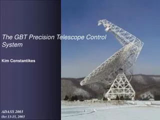
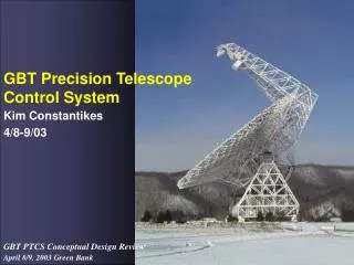
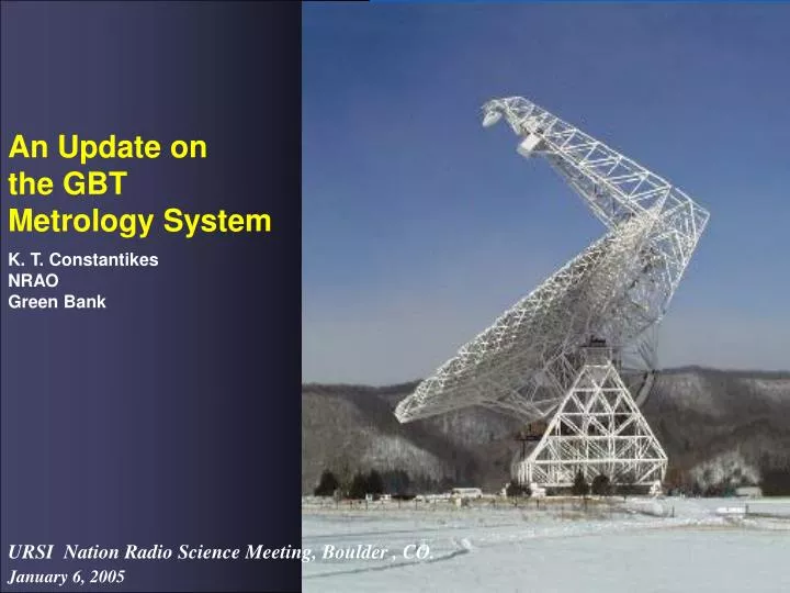
An Update on the GBT Metrology System K. T. Constantikes NRAO Green Bank
GBT Metrology System • New Approach • Parametric corrections using astronomy, e.g., Thermal Model • Parametric corrections using direct measurements, e.g., elevation axle pose • Combinations of angle, distance, and dynamical data, i.e. Quadrant Detector (QD), Laser Range Finder (LRF), Accelerometers for direct measurements of e.g. primary tilt • Combination of holography (surface figure at one elevation, no temp gradient) and few (> 6) direct measurements of primary to correct for smoothly varying FEA error (vs grav) and thermal errors • Fiducial and relayable tipping structure coordinate system (including orientation) tied to primary rim • Inclinometers on el axles tie all to topocentic frame, perhaps using a track map, perhaps direct alidade measurements • No rangefinders on ground • Fixed baseline range and angle measurements • System study underway, i.e., can pointing/focus/collimation/efficiency be met with new instruments and notional geometry of metrology components and telescope?
Current Instrument Set Structure Temperature Quadrant Detector Illuminator Structure Temperature Air Temperature Structure Temperatures (4) 3-Axis Accelerometer Structure Temperatures (3) Air Temperature Structure Temperatures (2) Structure Temperatures (4) Air Temperature Structure Temperatures (2) Air Temperature Quadrant Detector 2-Axis Inclinometers (2) 3-Axis Accelerometers (2) Elevation Encoder Structure Temperatures (2) Structure Temperatures (2) Structure Temperatures (2) Air Temperature Azimuth Encoder
Communications Infrastructure 2 RS485 to RS232 Transceivers (4 drops) Active Surface Actuator Control Room, Elevation Bearings RS232 to 802.x Concentrator (8 ports) Receiver Room 2 RS232 to 802.x Concentrators (16 ports) Active Surface Actuator Control Room 2 RS232 to 802.x Concentrator (16 ports) Vertex RS232 to 802.x Concentrator (8 ports) Alidade Level
Additional Design Constraints have been Addressed • RFI Mitigation and Testing • Thermal, Thermal/Mechanical Design • Maintainability • Availability (System MTBF) • Alignment/Calibration • Design for Installation
Structural/Air Temperature Sensors Environment Enclosure • 0.15 C accuracy, -35 to 40 C • 0.10 C interchangable thermistors • 0.01 C resolution, 1 sec sampling • 23 structure sensors • 5 air sensors , forced convection cells, ~ 5 sec time constant • RS232 communications • Automated testing (daily) • Structure thermal distortions • Vertical air lapse • Laser rangefinder group index calculations Thermistor in mounting slug Forced Convection Cell Mounted with VHB Tape and Delrin plate RFI Enclosure ESD Protection
Inclinometers • 2-axis (horizontal plane), both elevation bearings • 0.1” short-term accuracy, 0.01” resolution • ~1 sec damping, 17 Hz resonance • 5 Hz sampling rate, 0.3” noise at 5 Hz • Azimuth track maps • Real time measure/correct Az/El • Verify thermal effects • Wind force spring balance • Structural resonances
Inclinometers, Cont. Elevation Bearing Casting Accelerometer Cube Three Point, Spherical Washer and Shim Leveled Mount X Inclinometer Y Inclinometer
Accelerometers • 3-axis, elevation bearings and receiver cabin • MEMS torsion, capacitive readout, nickel • 2 micro-G/root Hz • 10 Hz sampling • 1 x 1 x 0.1 G dynamic range • 24 x 24 x 16 bit mixed signal ADC/microprocessor • Structural resonances • Receiver room vibration • Feed Arm motions • Vertical dynamics at El Bearings
Quadrant Detector (Version 3) Optical Tube, 800 mm fl lens, detector and TIA preamp assy. • Sub-arcsec angle-angle measurements, ~1000” FOV • ~5 Hz bandwidth, sampling at 10 Hz • Instrument noise ~ 0.2 arcsec (in lab) • Good relative measurements on ½ hour time scales • Degraded by turbulence, index gradients (19”/100m/1°K/m) • Feed arm position/motion WRT ~elevation shaft (tipping structure coordinates) • Structural resonances 5 Accuracy, 1.5Repeatability, 0.1 Resolution X-Z Translation Stage, Computer Control High Intensity Green LED Illuminator
QD V3 Performance 65 Hour calibration, 225 points (dithered) per affine transform estimate, 161 iterations 70mm dynamic range at 18m (~ 800”), air strongly mixed with fans Horizontal: zero point 1 = 0”.18, scale 1 = 0.06% Vertical: zero point 1 = 0”.85 (dominated by vertical index gradient), scale 1 = 0.1% Compare to PSD nonlinearity spec of 0.05% 1 measurement noise = 1”.1 at 10 Hz (Telescope configuration SNR, fan turbulence) Equivalent to 1.4” on sky @ 10 Hz Stationary telescope performance ~ 0”.2 to 0”.4 on sky @ 10 Hz (100 s linear detrend, clear day) 1700’/’ azimuth slew introduces ~ 2” of structural resonance modes.
Quadrant Detector (Version 4) Interim Configuration 4 channel BP filter and True RMS to DC Conversion 1x 24 bit sigma-delta, 3x 16 bit sigma-delta 512 Hz carrier modulation, 10 Hz sampling 7ppm local clock RS232 status, control, and data Time transfer over RS232/Ethernet Final Configuration Tunable filters (SCF) for three channels Three illuminator modulation frequencies Autocollimation and angle-angle measurements QD V4 with 500 mm fl catadioptric lens, temp control, TIA, 4x4mm PSD Analog Processor and Data Acquisition
IR Thermography Conduction into BUS ribs and hoops clearly visible, hot band in hoop direction ? Ripple due to conduction into BUS? ~ 2C cooler in Rcvr Room Shadow
Optical Telescope TE cooled micro-lens array full frame CCD mechanical shutter 765x510, 9 pitch 500 mm F/4 3”.8 IFOV 0.8° x 0.5° FOV 0.1 s min exposure USB 2.0 to Ethernet Power Supply Fiber Media Converter Primary use: Star tracking, i.e. orientation in inertial frame. Interpolate to ~ 1”, limiting magnitude better than 14 with 1 s exposure Implementation will include 5° tip-tilt stage, focus servo. Alternative to Inclinometers when dynamic range > 1° WRT gravity. Expect (95%) 2 stars > Mag 11 in FOV. NOT for use as “Pointing/Tracking Telescope”
Next Generation Laser Rangefinder PA Detector Bias Supply IF Subsystem TEC Controller, LD Power Supply Fiber Optic Switches DSP VGA Clock Synthesizers TE Cooler, Bias-T, Pigtailed Visible LD Detectors, Xmit and Rcvr Optics
Next Generation Laser Rangefinder, Cont. 1 kHz Offset @ 150 MHz, ~ 16 kHz BW Fiber Coupled JFET TIA Detector Xmit Aperture, ~ 1cm 24 Bit Digitized I/Q Rcvr Aperture, ~ 1 cm
Rangefinder Improvements • Frequency diverse (100-300 MHz), absolute range (incommensurate wavelengths) • Fiber optically coupled optics: • MEMS chopping, zero points, xmit to rcvr coupling @ 100 Hz • Fiber reference loop • Multiplexing multiple remote heads from one EO package • No longer share a single aperture- no need for polarization decoupling • Xmit and rcvr optics are small • No phase uncertainty associated with photon centroid on detector (group delay uncertainty in detector) • RFI Mitigation: No “bare” detectors or radiators, can use optical cutoff tube and fiber • Visible LD: • TE cooled to mitigate lasing wavelength changes (secondary group index error) • Mitigate eye hazard • Easy alignment • Looks cool…. • Might be marginally worse (?) for path loss, Mie scattering? • Easy to convert to NIR if needed
Rangefinder Improvements, Cont. • Diverged beam (~ 5 mrad) mitigates pointing problems, small scale turbulence • Fiber coupled optics could be mounted on existing pointing heads with fiber wrap • Much lower cost and volume: Telecom/OEM subsystems • Design Goals: Instrument noise less than group index fluctuation/uncertainty (0.3-1 ppm) • Current Measured Performance (single phase measurement): 23 on 20m path, 10Hz, 5 mrad beam, baseband13µ @ 1kHz offset • Instrument noise dominated by AM, shot noise limited (at detector diode) @ 1 kHz offset • Measurement noise dominated by index fluctuations @ 10 Hz • Disciplined measurement (e.g., structural modes) can have much lower measurement noise if needed
Acknowledgements, Etc. PTCS Instrumentation Team K. Constantikes, J. Ray, JD Nelson, J. Cromer, J. Shelton, R. McCullough, M. Stennes