Download
1 / 28
290 likes | 430 Views
Fundamental Dynamics of Digital Communications. Halim Yanıkömeroğlu Department of Systems & Computer Engineering Carleton University Ottawa, Canada. Outline. dB Notation The Big Picture: OSI Model Major impairments in communication systems Noise (AWGN) SNR

E N D
Fundamental Dynamics of Digital Communications HalimYanıkömeroğlu Department of Systems & Computer Engineering Carleton University Ottawa, Canada
Outline • dB Notation • The Big Picture: OSI Model • Major impairments in communication systems • Noise (AWGN) • SNR • Main goals of digital communications • MAC, RRM, RAN
What is wrong with the below figure? The detail is lost for the small values of the vertical axis!
What is wrong with the below figure? The detail is lost for the small values of the vertical axis! Want to show large and small values on the same scale?
Logarithmic versus Linear Scale What is wrong with the below figure? The detail is lost for the small values of the vertical axis! Want to show large and small values on the same scale? Use logarithmic scale (not linear scale)
dB Notation logc(a x b) = logc(a) +logc(b) logc(a ÷ b) = logc(a) –logc(b) Decibel notation: Field quantities: 20 log10 (.) Power quantities: 10 log10 (.) In this course: 10 log10 (.) x + (increased by 1,000,000 times increased by 60 dB) ÷ - (decreased by 50 times decreased by 17 dB) A [U] = (10 log10 A) [dBU] A [unitless] = (10 log10A) [dB]
dB Notation logc(a x b) = logc(a) +logc(b) logc(a ÷ b) = logc(a) –logc(b) Decibel notation: Field quantities: 20 log10 (.) Power quantities: 10 log10 (.) In this course: 10 log10 (.) x + (increased by 1,000,000 times increased by 60 dB) ÷ - (decreased by 50 times decreased by 17 dB) A [U] = (10 log10 A) [dBU] A [unitless] = (10 log10A) [dB] P [W] = (10 log10P[W]) [dBW] Ex: 2 [W] = 3 [dBW] P [mW] = (10 log10P[mW]) [dBm] Ex: 2 [mW] = 3 [dBm] P [dBW] = (P+30) [dBm] Ex: 5 [dBW] = 35 [dBm] 10 log10SNR = (10 log10(Psignal[mW] / Pnoise[mW])) [dB] 10 log10SNR = (10 log10Psignal) [dBm] – (10 log10Pnoise) [dBm] X [dBm] – Y [dBm] = Z [dB]; X [dBm] + Y [dB] = Z [dBm]
The Big Picture: OSI Model • The Open Systems Interconnection (OSI) model is a prescription of characterizing and standardizing the functions of a communications system in terms of abstraction layers. [Wiki] • For example, a layer that provides error-free communications across a network provides the path needed by applications above it, while it calls the next lower layer to send and receive packets that make up the contents of that path. Two instances at one layer are connected by a horizontal connection on that layer. [Wiki] http://www.hill2dot0.com/wiki/index.php?title=OSI_reference_model
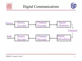
The Big Picture: OSI Model • The physical layer defines the means of transmitting raw bits rather than logical data packets over a physical link connecting network nodes. The bit stream may be grouped into code words or symbols and converted to a physical signal that is transmitted over a hardware transmission medium. • The physical layer provides an electrical, mechanical, and procedural interface to the transmission medium. The shapes and properties of the electrical connectors, the frequencies to broadcast on, the modulation scheme to use and similar low-level parameters, are specified here. [Wiki] http://baluinfo.com/networking/basic-networking-part-2/
Imprecise Terminology Often used synonymously in industry: Digital Communications (SYSC 4600) Transmission Technologies Physical Layer But they have slightly different meanings
Digital Communications Block Diagram Digital Communications, Sklar
Major Impairments in Communication Systems: A Simple Picture noise Transmitter Channel Receiver interference
Major Impairments in Communication Systems: A Simple Picture noise Transmitter Channel Receiver • Noise: always present interference
Major Impairments in Communication Systems: A Simple Picture noise Transmitter Channel Receiver • Noise: always present • Channel • Ideal channel (AWGN channel) • does not distort (change the shape of) the transmitted signal • introduces attenuation and delay interference
Major Impairments in Communication Systems: A Simple Picture noise Transmitter Channel Receiver • Noise: always present • Channel • Ideal channel (AWGN channel) • does not distort (change the shape of) the transmitted signal • introduces attenuation and delay • Non-idealities in channel • Distortion channel: distorts; may introduce self-interference • Fading channel: ideal channel with a time-varying impulse response interference
Major Impairments in Communication Systems: A Simple Picture noise Transmitter Channel Receiver • Noise: always present • Channel • Ideal channel (AWGN channel) • does not distort (change the shape of) the transmitted signal • introduces attenuation and delay • Non-idealities in channel • Distortion channel: distorts; may introduce self-interference • Fading channel: ideal channel with a time-varying impulse response • Interference (interference channel) • Major source of interference: other-user interference (co-channel interference) • Occurs mainly in wireless channels • Can be handled via signal processing, beamforming, RRM, … interference
Additive White Gaussian Noise (AWGN) AWGN is a channel model in which the only impairment to communication is noise AWGN: A linear addition of white noise with a constant spectral density and a Gaussian distribution of amplitude. [Wiki] The model does not account for channel impairments. However, it produces simple and tractable mathematical models which are useful for gaining insight into the underlying behavior of a system before these other phenomena are considered. [Wiki] Gaussian noise: Noise amplitude is a Gaussian distributed random variable (central limit theorem). White noise: An idealized noise process with a power spectral density independent of frequency.
Additive White Gaussian Noise (AWGN) Pnoise= k T B F = N0 B F k: Boltzmann’s constant = 1.38 x 10⁻²³ J/K T: Temperature in degrees Kelvin (generally taken as 290oK) N0: Noise power spectral density (constant) B: Bandwidth (signal bandwidth) F: Noise figure N0 =k T = -174 dBm/Hz Ex: 200 KHz channel (LTE resource block) F = 7 dB Pnoise= -114 dBm Broadband signal Pnoiseincreases White noise power spectral density SN(f) N0/2 Infinite total power (?) f
SNR, SINR • Signal-to-Noise Ratio: Defined at the receiver front end SNR = (signal power) ∕ (noise power) SNR = Psignal ∕ Pnoise SNR = (bit energy) ∕ (noise power spectral density) SNR = Eb ∕ N0 • Signal-to-Interference-plus-Noise Ratio: SINR = Psignal ∕ (Pinterference+ Pnoise) • Classical view: Threat interference as noise business as usual (use the theory developed for AWGN channel) • Modern view: Can we exploit the structure in the interference signal?
Wireless Channel: Fading Signal SNR AWGN channel: Ps: fixed SNR: fixed Fading channel: Ps: variable SNR: variable
Main Goal of Digital Communications SNR Transmitter Channel Receiver noise • Main Goal: For a given fixed SNR or an SNR distribution what operations should take place at transmitter and receiver to improve the performance? • Performance: Some meaningful metric • User metrics: (ultimately) eye, ear, feeling, smell, … • MOS (mean opinion scores) frame error rate (FER) packet error rate (PER) symbol error rate (SER) bit error rate (BER) • maximize SNR • resort to better transmission and/or reception techniques
Main Goal of Digital Communications SNR=10 dB
Main Goal of Digital Communications noise + TX Channel RX • How do you send information (reliably) through a channel? • For a given channel (medium), design TX and RX for best performance • Best? Maximize/minimize SER, BER, SNR, mutual information, … • Network metrics may be different than link metrics: • number of users, outage, sum (aggregate) rate, revenue, …
Main Goal of Digital Communications SNR Transmitter Channel Receiver noise • For a given fixed SNR (or an SNR distribution) what operations should take place at transmitter and receiver to improve the performance? • Pulse shaping • Modulation, demodulation • Channel coding, decoding • Diversity • Equalization • …
Channel Capacity Channel capacity, Shannon capacity, information-theoretic capacity C = log2(1+SNR), bits per second per Hertz Non-constructive existence theorem Developments Shannon’s original formulation: 1948 Block codes, convolutional codes, … Turbo codes (1993) Low-density parity check (LDPC) codes (1963, 1996) Polar codes (2008)
Bandwidth vs Rate T: Pulse duration, R: Rate R = 1/T W: Bandwidth Inverse relation between T and W Direct relation between R and W Narrow pulses (high rates) Large bandwidth
MAC, RRM, RAN Want SNR ↑ ? PS ↑and/or Pn ↓ (limited control on Pn) Want SINR ↑ ? PS ↑ and/or PI ↓ and/or Pn ↓(limited control on Pn) How can we increase PS ? How can we decrease PI ? Answer: Medium Access Control (MAC) [layer 2] Radio Resource Management (RRM) [layer 2] Radio Access Network (RAN) How do we compute PS ? Propagation modeling