Download
1 / 25
250 likes | 320 Views
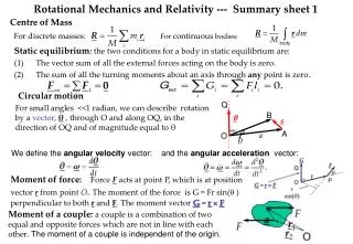
&. Analysis of Systems in Static Equilibrium. Procedure:. Draw a schematic diagram of the system Draw the free-body diagram (FBD) Chose a cartesian coordinate system (x,y,z). For each FBD apply: Include Directions and Physical Units If # of equations equal # of unknowns; Solve!.

E N D
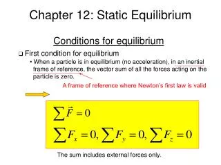
& Analysis of Systems in Static Equilibrium Procedure: • Draw a schematic diagram of the system • Draw the free-body diagram (FBD) • Chose a cartesian coordinate system (x,y,z). • For each FBD apply: • Include Directions and Physical Units • If # of equations equal # of unknowns; Solve!
Vector Operations • The parallelogram law; • The commutativity principle; • Vector addition: c=a+b=b+a (commutativity) • Vector subtraction: d=a-b • Vector products • The dot product: e=ab=ba (commutativity) • The cross product: f=axbbxa • Vector products are distributive z k j i y x
a Vector Products • The dot product yields a scalar • Cross product in explicit form: • Geometrical description of the cross product would be a vector perpendicular to the plane formed by F1 and F2 and its absolute value would be:
Moment of a force The moment of a force about a point is the applied force times the distance between the point and the line of action of the force. or in a planar case, the magnitude of a moment:
Scalar Representation of a Moment and the direction is determine as described below Moment of a force is represented by a vector perpendicular to the plane of the force and the position vector .
Moment Vector Three-Dimensional Case:
Moment Addition Collinear moments addition
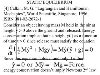
Gravitational Force (Weight) The force exerted by the Earth on an object The gravitational force is some times expressed as: Where: g = 9.81 m/s2 The Ground Reaction N (Newton’s 3rd Law)
Gravitational Force (Cont.) Often the relationship: Is substituted based on the fact that the dynamic equation for a free object in the gravitational field is:
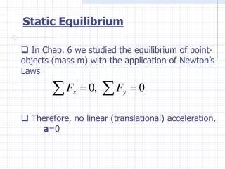
Z P Wt O X R1 R2 Y Problem #1 A person standing in a bus and holding single-handedly to an overhead rail experiences the forces depicted in the figure. The mass of the person is 75 Kg and the coordinates of the points of application of the forces R1, R2, P, in meters are: R1(-0.2;-0.15;0) R2(+0.2;+0.15;0) P(0.25;0.35;1.85) And the measured forces (in Newtons) are: R1= -5i-75j+300k R2= 75i+25j+375k The person is in static equilibrium which is satisfied by the balancing action of the force P. Determine: The force vector P The magnitude of the moments exerted by the forces R1, R2 and P, on the lumbar junction O, located at: O(-0.1;-0.15;+0.8) The moment acting on the lumbar junction Wt=50% Body weight (Weight of the upper body) D=15 cm
6 5 7 8 L1vertebrae r4 4 3 9 r3 rLumbar 2 r2 z r1 1 0 x y Position
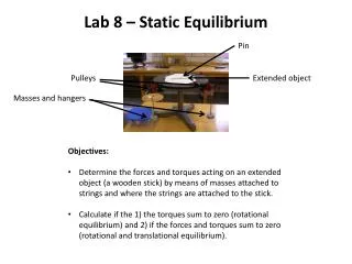
Hinge Roller The Modeling Concept (i) A rigid body in static equilibrium is subjected to active and reactive forces and moments. Active forces & moments: External and Gravitational. Reactive forces & moments: Constraint forces Constrains:
The Modeling Concept (ii) Constraints and Reactions
Fm Quad Fm Calf Fn Fm Achil Constraints and Reactions (iii) Flexible Member (cable, chain, rope, muscle): Can apply tensile forces only.
Distributed Force or Pressure When one object is in contact with another, the force of interaction is distributed over the contact surface. This will be described as a “distributed force”, “bearing stress”, or “pressure”.
Pressure in Biomechanics (ii) “Pressure Ulcers” or “pressure sores” affects people who are confined to bed for extended period of time, or wheelchair users, or those with sensory deficiency such as diabetics.
Muscle Stage 1 Skin Bone Stage 2 Stage 3 Pressure in Biomechanics (iii) Bed Sores A bedsore is breakdown of skin and underlying tissue to form sores and ulcersdue to persistant static pressure. Bedsores are also known as pressure sores, decubitus ulcers, pressure ulcers and pressure wounds. Stage 4
Pressure in Biomechanics (iv) The Prosthetic Interface
N K G F H • H(0.45; -0.1; 1.36) • I(0.45; -0.1; 1.05) • J(0.45; 0.34; 1.08) • K(-0.45; -0.1; 1.38) • L(-0.45; -0.05; 1.05) • M(-0.45; -0.02 ;0.81) L • A(0.15; 0; 0) • B(0.15; 0.1; 0.4) • C(0.15; 0; 0.9) • D(0; 0; 0.9) • E(0; 0; 1.0) • F(0; -0.15; 1.38) J E I 10kg D C M B Z Y A X Class Problem #6 A person stands upright and is holding a metal ball weighing 10Kgs. Considering the weight of his body segments, their positions and their dimensions given in the table, determine the force and the moment exerted on the Sacro-Illiac junction designated by the point D. The following points are given:
Anthropometric Data on Body Segments * Data are per single limb ** Relative distance of C.M. (measured from the lower numbered joint)
Z X Y F F 1 2 Homework # 2 The person described in the figure weighs 700 Newtons and is 170 centimeters tall. He is subjected to the gravitational forces and the ground reaction forces F1 and F2 . Considering that F1 has the following components: (1) Assign angular positions to the body segments and obtain their centers of mass and masses, from the table used in assignment #1 (assume the transverse distance between the hips to be 25 centimeters) and determine the following: • Position of the right hip joint (the leg that is ahead); • The net forces acting on an imaginary section through the hip; • Moment acting at the knee; • Moment and force acting at the hip. (2) Check if the person is in a static equilibrium. (3) Determine the moments of the ground forces with respect to the center of mass.
Homework Assignment #2, Cont. • Get a textbook of anatomy, identify the major muscle groups that activate the hip, knee and ankle. • Determine which muscle are responsible for the flexion- extension of the knee and draw a geometrical model that will help you calculate the forces in these muscles when a person puts his full weight on one leg.