Download
1 / 15
500 likes | 1.66k Views
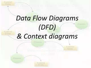
Data Flow Diagrams (DFD). DFDs are about depicting the movement of data in an information system. Synonyms of DFDs are bubble chart, process model, and transformation graph. DFDs have four symbols: data flows, processes, data stores, and external entities (“entities”). DFD Symbols.

E N D
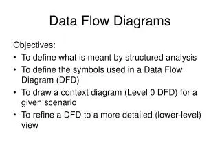
Data Flow Diagrams (DFD) • DFDs are about depicting the movement of data in an information system. • Synonyms of DFDs are bubble chart, process model, and transformation graph. • DFDs have four symbols: data flows, processes, data stores, and external entities (“entities”).
DFD Symbols Descriptive singular nouns Examples: Registrar Suppliers MS [Manufacturing System] FIS [Financial Info. System] A strong action verb + object clause that defines what the work is being performed on (or for) Examples: Validate Student Information Process Customer Order Calculate Order Cost Check Customer Credit Create New Member Account
DFD Symbols Avoid physical names such as file cabinets, database file, etc. Examples: Orders Members Accounts Receivables • Descriptive nouns and noun phrases that are singular. • Should be unique • Use adjectives and adverbs to describe how processing changed data flow • Examples: Employee address • Membership application • Accepted order Data Flows
Process • A process is used to transform an input to an output. • We are interested in WHAT work or action is being performed (Logical Design) and not on WHAT or WHO is doing that activity (Physical Design) • The physical implementation of the system are not shown in a DFD.
Data Flows • Data flows show inputs of data to a process, or the outputs of data from a process. • In addition, data flows are used to create, delete, or update of data in data storage. • Telephone calls, business forms, Web forms, reports, may create data flow(s). • We are not interested in physical data flows.
Data Flows • Do not leave any data flow unnamed. If you cannot give a data flow a reasonable name, it probably doesn’t exist! • Data flow names should describe the data flow without describing how the flow is or could be implemented. • All data flows must begin or end at a process because data flows are inputs and outputs of a process.
External Entities • Define the boundary of the information system and shows places where the system interfaces with its environment. • Defines an organizational unit, a person, or other organization that lies outside the scope of the project, but that interacts with the system. • Provides input and receives output. • You may duplicate external agents on DFD to avoid crossing data flow lines.
Data Store • A business needs to store data about • Persons: Agency, Contractor, Customer. • Places: Sales region, Building, Room. • Objects: Book, Machine, Part. • Events: Application, Class. • Concepts: Account, Bond, Fund. • You may duplicate data stores on a DFD to avoid crossing data flows lines (max. 3 duplications advised).
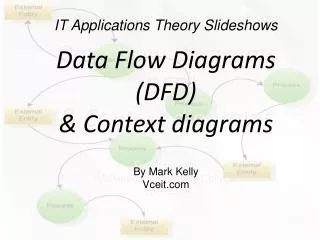
Context Diagram(Level 0 Diagram) • Shows the scope of the IS project. • Shows systems’ interaction with the external environment. • Includes only one process. • Includes only external data stores. • External data stores can not be changed (“read-only”).
Input not sufficient to produce this output A “Gray Hole” Common Errors No Output A “Black Hole” No Input A “Miracle”