Download
1 / 24
320 likes | 497 Views
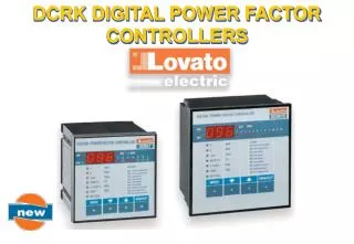
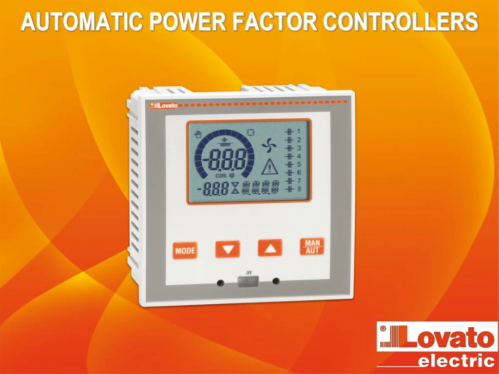
AUTOMATIC POWER FACTOR CONTROLLERS. AUTOMATIC POWER FACTOR CONTROLLERS. DCRL3 - 3 BUILT-IN STEPS DCRL5 - 5 BUILT-IN STEPS ICON LCD WITH BACKLIGHT Alarm messages in 6 languages OPTICAL PORT ON FRONT EXPANDIBILITY WITH EXP… MODULES RS232, RS485, USB communications interface Additional steps

E N D
AUTOMATIC POWER FACTOR CONTROLLERS • DCRL3 - 3 BUILT-IN STEPS • DCRL5 - 5 BUILT-IN STEPS • ICON LCD WITH BACKLIGHTAlarm messages in 6 languages • OPTICAL PORT ON FRONT • EXPANDIBILITY WITH EXP… MODULES • RS232, RS485, USB communications interface • Additional steps • Digital outputs • High accuracy TRMS measurementsWide selection of electrical measures, including voltage and current THD with harmonic analysis up to 15th order. • Wide power supply range (100-440VAC)Voltage input separated from power supply, suitable for VT connection in medium-voltage applications.
AUTOMATIC POWER FACTOR CONTROLLERS BACKLIGHT ICON LCD • Helpful in bad lighting conditions • Main measurements regarding power factor correction viewed • The user can select the default measurement to display • With rotation mode activated all the measurements rotate automatically every 5 seconds on the display • Possibility to signal the alarm with backlight flashing. • In presence of alarm, a scrolling text appears on the display in 6 selectable languages.
AUTOMATIC POWER FACTOR CONTROLLERS Manual mode Inductive / capacitive Automatic mode Cooling fan status Output status Main display Step status Bar graph Active alarm Secondary display Alphanumeric display BACKLIGHT ICON LCD
AUTOMATIC POWER FACTOR CONTROLLERS BACKLIGHT ICON LCD SCREEN • The bar-graph can be programmed with three different viewings: • kvar ins/tot: amount of kvar actually inserted, with reference to the total reactive power installed in the panel • Curr act/nom: Percentage of actual plant current with reference to the maximum current of the CT • Delta kvar: Bar graph with center zero. It represents the positive/negative delta-kvarneeded to reach the setpoint, compared to the total kvarinstalled. • The icons on the right side of the display indicate the step status: • The controller displays the imminent connection or disconnection of the steps by their identification number (left) flashing • The flashing can last for some time in cases in which the insertion of a step is not possible due to the reconnection time (discharge time of the capacitor). When an alarm is generated, the display will show an alarm icon, the code and the description of the alarm in the language selected.
AUTOMATIC POWER FACTOR CONTROLLERS BACKLIGHT ICON LCD Parameters Bar graph Setup menu Measurements
AUTOMATIC POWER FACTOR CONTROLLERS OPTICAL PORT ON FRONT • Advantages • No need to disconnect the panel power supply to connect with the device • Electrical safety (no physical connection) • Easy access to the unit from the front. CX01 – IR to USB converter CX02 - IR to Wi-Fi dongle
AUTOMATIC POWER FACTOR CONTROLLERS OPTICAL PORT ON FRONT CX01 • PC link through USB (CX01) or WiFi (CX02) for: • Programming • Diagnostics • Data downloading • Firmware upgrade. • Using CX02 (WiFi), the following is possible: • Project upload/download • Controller cloning. CX02
AUTOMATIC POWER FACTOR CONTROLLERS • DIMENSIONS • Front panel: 96x96mm • Depth: 65mm (with or without modules).
AUTOMATIC POWER FACTOR CONTROLLERS • EXPANSION MODULES • Plug-in connection at the back of the base unit • Power supplied by the base unit • Increase the number of outputs • Add communication features. • Additional steps • EXP10 06: • 2 415 VAC 1,5A relays • NO and COM contacts for each output. • Digital output modules • EXP10 03: • 2 250VAC 5A relays • NC, NO and COM contacts for each output. • Communication modules • EXP1010 – Opto-isolated USB interface • EXP1011 – Opto-isolated RS232 interface • EXP1012 – Opto-isolated RS485 interface.
AUTOMATIC POWER FACTOR CONTROLLERS tool-less installation Fixing clips
AUTOMATIC POWER FACTOR CONTROLLERS EXP 8000 Removable plastic accessory for labelling tool-less installation
AUTOMATIC POWER FACTOR CONTROLLERS MAIN CHARACTERISTICS • Auxiliary power supply • Rated voltage: 100…440VAC. • Voltage inputs • 2 inputs (L1, L2) • Voltage range: 85…720VAC (L-L). • Voltage and current harmonic analysis • THDV • THDI • Approvals and compliance • IEC/EN 61010-1, IEC/EN 61000-6-2 IEC/ EN 61000-6-3 • UL508 and CSA C22.2 n°14 • cULus pending • EAC • Current inputs • 1 input • CT secondary rated current: • /5A or /1A (selectable) • Current range: • 125mA…6A (/5A), 25mA…1.2A (/1A) • Output relays • 4 N/O + 1 C/O = 5 relays • (expandable up to 7 with EXP1006) • 2 N/O + 1 C/O = 3 relays • (expandable up to 5 with EXP1006).
AUTOMATIC POWER FACTOR CONTROLLERS • SELLING POINTS • User Interface • Backlight icon display with more information • Excellent legibility on bad light condition • Backlight flashing in case of alarm • Viewing of texts, measurements, and alarms in 6 languages (English, Italian, French, Spanish, Portuguese, German) • Programmable bar graphs programmable. • Installation • Wide voltage range (85…720VAC) in compact size • The installation depth does not change with the EXP expansion installed • Installation without tools • Simple programming from front panel.
AUTOMATIC POWER FACTOR CONTROLLERS • SELLING POINTS • Application • Single-phase and three-phase installation • Cogenerating systems with dedicated setpoint • Medium voltage application with voltage transformers (VT) • Measurement viewing relevant VT primary • Device settings considering the primary side of the VTs (i.e. capacitor bank reactive power, protections, etc.) • 2-level password to protect functions and parameter setup • Reduced number of switchings by algorithm • Equal usage of steps with the same reactive power • THDV, THDI measurement and harmonic analysis up to 15th order • Advanced protection for capacitor banks.
AUTOMATIC POWER FACTOR CONTROLLERS • SELLING POINTS • Expandability • Basic controller functionality can be easily extended using EXP series expansion modules • Increase number of steps • Adding communication features. • Optical communication port • Standard USB or Wi-Fi point • Communication with PC, smartphone, and tablet to carry out programming, diagnostics and data download without removing power to the electric panel.
AUTOMATIC POWER FACTOR CONTROLLERS DCRL vs DCRK DCRK3 DCRK3 240 DCRK3 440 DCRK3 480 DCRK3 525 DCRK5 DCRK5 240 DCRK5 440 DCRK5 480 DCRK5 525 DCRK7 DCRK7 240 DCRK7 440 DCRK7 480 DCRK7 525 CT secondary/5A or /1A without special code management DCRL3 DCRL5 DCRL5 +EXP1006
AUTOMATIC POWER FACTOR CONTROLLERS DCRL vs DCRK
AUTOMATIC POWER FACTOR CONTROLLERS • NEW MEASUREMENTS AND PROTECTIONS • Active and apparent power • Current and voltage harmonics analysis • THD capacitor current • THDV,THDI • With the addition of these measurements and the alarms regarding THD max (voltage and current), the user can completely know the status of the system • This information can be helpful for advanced analysis in case of system anomalies to introduce the necessary corrections. • var-measured value per step • Number of switchings per step • Connection time per step • These measurements and the relative alarms, maintenance request and capacitor bank failure provide useful information for the power factor correction system supervision • This information can be used to schedule the maintenance of the installations.
AUTOMATIC POWER FACTOR CONTROLLERS DCRL vs DCRG8
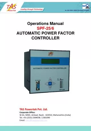
AUTOMATIC POWER FACTOR CONTROLLERS SETUP SOFTWARE DCRJ SW You can use the DCRJ Remote control software to transfer set-up parameters from the DCRL to the hard drive of the PC and vice versa and read the measurements.
AUTOMATIC POWER FACTOR CONTROLLERS SUPERVISION AND CONTROL SOFTWARE • Web based • Server – Multiclient structure • One software for many devices (multichannel) • Synergy is a supervision and control software for: • Electrical parameters (from voltage and current to energy) • Environmental and process parameters (temperature, pressure, flux). • Beyond providing data in tables and graphic pages, it offers: • alarm generation • chart plotting • command sending to devices.
AUTOMATIC POWER FACTOR CONTROLLERS APPLICATIONS FOR SMARTPHONES AND TABLETS • Lovato applications let the user: • Set up the device • Send commands to the device • Read values • Download statistics and events • Send the retrieved data by e-mail. • Wi-Fi connection between the smartphone/tablet and CX02 • The user is guided to be connected to the device • Automatic application upgrade if an Internet connection is available • Compatible with iOS and Android.
AUTOMATIC POWER FACTOR CONTROLLERS Thanks for your attention! www.LovatoElectric.com