Download
1 / 42
420 likes | 578 Views
Vertical Test Stand for ILC Cavities. Ruben H. Carcagno (for the VTS Team) ILC R&D Meeting Wednesday 11, 2006. Outline. Need for an ILC Vertical Test Stand (VTS) ILCTA_IB1_VTS Project Status Plan to increase VTS throughput. 26.5”. ILC Vertical Test Stand Function.

E N D
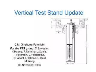
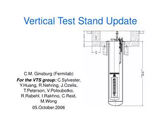
Vertical Test Stand for ILC Cavities Ruben H. Carcagno (for the VTS Team) ILC R&D Meeting Wednesday 11, 2006
Outline • Need for an ILC Vertical Test Stand (VTS) • ILCTA_IB1_VTS Project Status • Plan to increase VTS throughput ILC R&D Mtg 10-11-06
26.5” ILC Vertical Test Stand Function Low-power test of “bare” Cavities Measure Q vs. T (Tmin~1.5 K) Measure Q vs. Eacc at 2 K Only way to verify that an ILC cavity meets Q, Eacc specifications! ILC R&D Mtg 10-11-06
Cavity Preparation Processes not Reproducible More than one vertical test/processing cycle is now needed per cavity to reach maximum performance Avoiding field emission is an ongoing struggle ! Graph from Lutz Lilje, KEK Mtg Sep. 06 ILC R&D Mtg 10-11-06
ILC Cavity Baseline Yield too low around ILC performance baseline ILC R&D Mtg 10-11-06
Main Sources of Reproducibility Problems • Imperfections in final surface treatment, • e.g. electropolishing (EP) • final rinsing • Field Emission from particle contamination • e.g. assembly processes • sulphur from EP acid • Thermal breakdown of superconductivity from material or manufacturing defects • Weld Problems at new industry • Deviation from specification • Insufficient quality control From Lutz Lilje, KEK Mtg Sep. 06 ILC R&D Mtg 10-11-06
Vertical Test Stand Need • The need of making gradients more reproducible is a top priority • “S0” Goal: Achieve 35 MV/m at Q0=1010 in 9-cell cavity in vertical dewar tests (low-power) with a sufficient yield (> 90% for more than 100 preparation and test cycles). Two parts: • S0.1: Tight loop to improve “final preparation” yield • S0.2: Production-like activities to determine overall yield for cavity materials, fabrication and full cavity processing • S0/S1 Task Force • Hitoshi Hayano (KEK), Toshiyasu Higo (KEK),John Mammosser (JLab) Hasan Padamsee (Cornell), Marc Ross (FNAL), Kenji Saito (KEK), Lutz Lilje (DESY) • Wiki Site: http://www.linearcollider.org/wiki/doku.php?id=rdb:rdb_external:rdb_s1_home • Eventually a dedicated facility with sufficient redundancy and flexibility is desirable to have fast turn-around of cavity tests. From Lutz Lilje, KEK Mtg Sep. 06 ILC R&D Mtg 10-11-06
Projected Total Number of Cavity Processes(from S. Mishra, ART FY08-09 Planning Meeting at SLAC 9/13/06) http://ilcagenda.cern.ch/materialDisplay.py?contribId=7&materialId=slides&confId=1114 Each process requires a Cavity Vertical Test ILC R&D Mtg 10-11-06
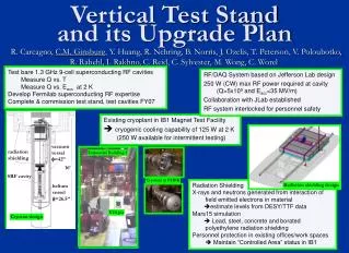
26.5” Vertical Test Stand at Fermilab • One VTS under construction in ILCTA_IB1 • Initial operation with single, bare, 1.3 GHz ILC 9-cell cavities but designed to accommodate up to two cavities (only one RF-powered at a time) • Maintain “Controlled Area” status in IB1 • < 5 mrem/hr immediately outside the shielding • <0.25 mrem/hr in normal working areas • VTS Team: Camille Ginsburg (Project Physicist), Cosmore Sylvester (Project Engineer), Y.Huang, R.Nehring, J.Ozelis, T.Peterson, V.Poloubotko, R.Rabehl, I.Rakhno, C.Reid, M.Wong • Expected to start operation in mid-2007 ILC R&D Mtg 10-11-06
Radiation Shielding Designed • X-rays estimated from DESY data • Design from MARS15 simulation (I. Rakhno) has been approved by ES&H and is available as Fermilab-TM-2350-AD • Kamran Vaziri (ES&H) is our point-of-contact for radiation safety and permissions • Tritium production negligible • “Controlled area” satisfied ILC R&D Mtg 10-11-06
IB1 Civil Construction Complete(August 2006) ILC R&D Mtg 10-11-06
VTS Layout LLRF Cryo & Rad Inst. HPA & SW PC/PXI & RF Instr. ILC R&D Mtg 10-11-06
Cryostat Order Placed • Design and procurement readiness review took place on May 16 (Review team: J. Theilacker (Chair), T. Nicol, P. Pfund) • Two bids received: Meyer Tool and PHPK • After technical & price bid evaluation, PHPK selected • Purchase order placed Sept. 20 • Magnetic Shielding design complete and ready for procurement • Cryostat installation in VTS pit scheduled for March 2007 ILC R&D Mtg 10-11-06
RF Design Complete • Based on proven Jlab VTS RF system with improvements • Collaboration with Jlab established (added to Jlab MOU scope) • Reviewed on August 24. Review Team: R. Pasquinelli (Chair), J. Steimel, B. Chase, C. Worel, J. Reid, W-D. Moeller) 24.August • Most procurements have been placed • RF personnel safety interlocks in progress, with Chuck Worel (AD/ES&H) ILC R&D Mtg 10-11-06
Tie-in Design to IB1 Cryo System Complete • Most procurements have been placed • Process Control Logic Description Document available Detailed P&ID ILC R&D Mtg 10-11-06
Radiation Shield Lid Cover under Mechanical Design Example: Cornell VTS Cover ILC R&D Mtg 10-11-06
Top plate insert under design Example: Jlab VTS Top Plate Example: Cornell VTS Top Plate ILC R&D Mtg 10-11-06
Project Schedule Detailed MS Project Schedule Available ILC R&D Mtg 10-11-06
FY07 Activities • Receive cryostat, install magnetic shielding, and install into prepared pit • Procure and assemble top-plate assembly • Fabricate and install radiation shield lid • Install Cryogenics • Install RF, controls, instrumentation, etc. • Install radiation safety interlock system • Commission test stand • Begin cavity tests ILC R&D Mtg 10-11-06
IB1 VTS Capacity • Given the increased need for VTS throughput to satisfy S0 R&D goals, a team was put together to analyze the IB1 VTS peak capacity, feasibility of additional VTS stands, and IB1 infrastructure upgrades requirements • Analysis Team: Ruben Carcagno, Camille Ginsburg, Yuenian Huang, Arkadiy Klebaner, Joe Ozelis, Tom Peterson, Clark Reid, Cosmore Sylvester • This work is in progress, and following is a status of preliminary findings and recommendations ILC R&D Mtg 10-11-06
Single VTS Throughput • Throughput Assumptions: • Single shift operation • Cavity arrives hermetically sealed • 120 °C bakeout done prior to IB1 delivery • “Production” Q vs. E test only (e.g., no 8-hr pause at 100K during cooldown to determine degree of H contamination (Q-disease)) • Two cavities in a VTS cryostat • Only one RF ON cavity test at any given time ILC R&D Mtg 10-11-06
Unconstrained Test Cycle Schedule (Nearly) Unattended Operation ~ 28 hours Attended Operation ~ 11 hours TOTAL (unconstrained) ~ 39 hours ILC R&D Mtg 10-11-06
Adding Constraints • Shift Operations • 11 hours of attended operations require a minimum of 23 hours because of 12-hour pause between 8-hour shifts • Inefficiencies (idle time due to shared resources, equipment availability, troubleshooting) • Add ~ 24 hours • Total Test Cycle ~ 75 hours or ~ 3.12 work days for two cavities. • Assuming 8 work weeks of maintenance and other facility down time per year: Single VTS throughput ~ 70 double-cavity test cycles per year (140 test processes) ILC R&D Mtg 10-11-06
How to (quickly) increase throughput? • Two additional VTS stands can be added to the IB1 facility by relocating the ILCTA_IB1 Horizontal Test Stand (HTS) planned for FY07 to ILCTA_MDB. • Throughput can increase to ~ 3x140 = 420 test processes per year • Some throughput increase might be possible by adding shifts and removing inefficiencies • Substantial additional throughput increase only possible by building modifications and/or a building addition. Cryogenic capacity becomes a limiting factor (tie-in to CHL after Tevatron shutdown?) ILC R&D Mtg 10-11-06
Phased Approach for a Vertical Cavity Test Facility (VCTF) • Phase I • Complete VTS under construction by mid-2007 • Phase II • Add two more (nearly) identical VTS stands by mid-2008 • Phase III • Add one or more high-throughput VTS stands in a modified or new building addition plus additional cryogenics capacity ILC R&D Mtg 10-11-06
IB1 SRF Test Area Layout Vertical Test Area (FY06) (Bare Cavities) Existing Cryo Piping ILC R&D Mtg 10-11-06
IB1 Layout for Phase II Trench for cryo piping Door Radiation Lid “park” area Stairs Additional VTS Vertical Magnet Test Facility (VMTF) Staging Area VTS under construction Tie-in to test stands cryo distribution box ILC R&D Mtg 10-11-06
Conceptual 3-D Model of a 3-VTS Facility plus staging area ILC R&D Mtg 10-11-06
VTS Staging Area Platform with 2 top plates per VTS needed for multiple VTS facility Example: Jlab VTS Platform Example: KEK VTS Platform ILC R&D Mtg 10-11-06
IB1 FY07 Test Schedule and Civil Construction(Window during Feeder 47 and Cryo Maintenance Upgrade April-May 07) ILC R&D Mtg 10-11-06 : Magnet Dept. Support : SRF Dept. Support : IB1 Maintenance : New development needed for test
IB1 Infrastructure Considerations • The IB1 Test Facility shares cryogenics and people with a very active Magnet Test Facility (MTF) • It is essential to decouple cryogenic operations between MTF and the Vertical Cavity Test Facility (VCTF) • There should be adequate cryogenic resources available to sustain both MTF and VCTF test programs. This includes both LHe inventory and pumping capacity for superfluid operation ILC R&D Mtg 10-11-06
Infrastructure Requirements • Add a third vacuum pump to increase pumping capacity from 6 g/s at 20 Torr to at least 10 g/s • Add a compressor/purifier at the outlet of the vacuum pump system to mitigate contamination risk • Add more GHe storage capacity to store the majority LHe inventory as gas • These upgrades are needed to meet peak throughput of either one VTS or multiple VTS ILC R&D Mtg 10-11-06
Current Plan for single VTS integration to IB1 ILC R&D Mtg 10-11-06
Multiple VTS Integration to IB1 ILC R&D Mtg 10-11-06
How much pumping? • For baseline E = 35 MV/m, Q0 = 1010 the power dissipation is: • Substantial margin is needed to continuously operate at higher gradients and/or lower Q. • Constraints: JT Heat Exchanger and Pumping Capacity (6 g/s at 2 K) ILC R&D Mtg 10-11-06
JT Heat Exchanger Pumping Limit With the current VTS JT Heat Exchanger design, practical limit for continuous 2K operation is around 8 to 10 g/s (160 to 200 Watts) due to excessive shellside pressure drop To remove more than 200 Watts (10 g/s pumping) continuously, a redesigned JT Heat Exchanger must be used in future VTS. This may require an adjustment to the cryostat (and pit) diameters. ILC R&D Mtg 10-11-06
IB1 Pumping Capacity • Installed: 6 g/s at 20 Torr • Kinney Pump I: 4 g/s • Kinney Pump II: 2 g/s • Need more pumping: • Margin for higher gradients and/or lower Q continuous operation • Simultaneous operation of superfluid magnet test and cavity test • Need a new, dedicated, large (13 g/s) vacuum pump for VTS stands, similar to the one installed at ILCTA_MDB for HTS testing. Use existing pumps for magnet testing. Kinney Pump Installed at ILCTA_MDB for the HTS ILC R&D Mtg 10-11-06
Compressor/Purifier • Contamination is already one of the largest reason for IB1 cryo system unscheduled downtime and loss of efficiency • Addition of sub atmospheric test stands will make this problem worse • Need a high pressure compressor andpurifier skid to remove all contamination at the outlet of vacuum pumping system (like the one recently installed at ILCTA_MDB). • This is a high-priority item Compressor/Purifier installed at ILCTA_MDB at the outlet of Kinney Pump for HTS Testing ILC R&D Mtg 10-11-06
LHe Availability • IB1 cryo system LHe make rate: ~ 250 l/hr (9 g/s) • VTS LHe consumption per test cycle: ~ 2,000 l (equivalent to 27 l/hr for a 75-hr test cycle) • For three VTS stands operating continuously: 3x27 = 81 l/hr • On average, there is still ~ 170 l/hr LHe make rate available to support magnet testing. Need adequate LHe and GHe buffer storage to satisfy peak demands for both Magnets and Cavity testing programs ILC R&D Mtg 10-11-06
IB1 LHe and GHe storage • A 10,000 liter He dewar stores up to 7,000 liter of LHe • Three 30,000 Gallon GHe tanks store up to 3,900 LHe equivalent He gas (only 55% of LHe inventory capacity) • Need two more 30,000 Gallon tanks to store the majority of LHe inventory as gas ILC R&D Mtg 10-11-06
Preliminary M&S Cost Estimate ILC R&D Mtg 10-11-06
VTS Project Challenges • Aggressive schedule (Phase I ready by mid-2007, Phase II by mid-2008) • Must minimize disruption to the Magnet Test Program • Requires experienced resources outside of T&I department (e.g., AD-Cryo, FESS) • Must be a Laboratory High Priority Project • Requires adequate funding • Schedule-driven nature of project dictates need to procure turn-key skids from industry as much as possible (e.g., Compressor/Purifier, Kinney Pump) ILC R&D Mtg 10-11-06