Download
1 / 1
10 likes | 208 Views
C+C Crate. Machine. 2D Pixel Detector. Crate Processor. C+C Master. Timing Receiver. Controls TCP/IP Network. Readout Crate. 600 μ s. 64k Pixel Unit. 64k Pixel Unit. Detector Unit. Detector Unit. Detector Unit. Detector Unit. Detector Unit. Detector Unit. 99.4ms.

E N D
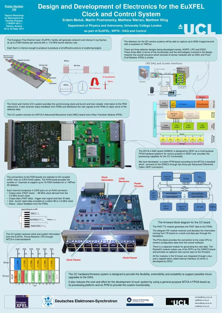
C+C Crate Machine 2D Pixel Detector Crate Processor C+C Master Timing Receiver Controls TCP/IP Network Readout Crate 600μs 64k Pixel Unit 64k Pixel Unit Detector Unit Detector Unit Detector Unit Detector Unit Detector Unit Detector Unit 99.4ms Backend Processing X-ray photons 100 fs Crate Processor Train Builder Train Builder Train Builder 200ns FEL Process Switch PC PC PC PC PC PC Storage C+C Slave Deutsches Elektronen-Synchrotron Design and Development of Electronics for the EuXFEL Clock and Control System Poster Number 104 Topical Workshop on Electronics for Particle Physics ( TWEPP-2011 ) Vienna, Austria 26 to 30 Sept. 2011 Erdem Motuk, Martin Postranecky, Matthew Warren, Matthew Wing Department of Physics and Astronomy, University College London as part of EuXFEL, WP76 : DAQ and Control The European Free Electron laser (EuXFEL) facility will generate coherent and intense X-ray flashes at up to 27000 flashes per second with a ~4.5 MHz bunch delivery rate. Each flash is intense enough to produce to produce a full diffractive picture of scattering targets. The detectors for the 2D camera systems will be able to capture up to 5000 images/second with a resolution of 1MPixel. There are three detector designs being developed namely, AGIPD, LPD and DSSC. These three differ in terms of the functionality and the technologies involved in the design, however the overall structure which consists of sensor modules with an ASIC and Front End Modules (FEM) is similar. The Clock and Control (CC) system provides the synchronising clock and bunch and train related information to the FEM electronics. It also receives status feedback from FEMs and distributes the veto signals to the FEMs to reject some of the detector data The CC system consists of a MTCA.4 Advanced Mezzanine Card (AMC) board and a Rear Transition Module (RTM) The MTCA.4 AMC board (DAMC2) is designed by DESY as a multi-purpose FPGA hardware platform for various projects in DESY and provides the processing capability for the CC functionality. We have developed a custom RTM board according to the MTCA.4 standard which connects to the DAMC2 through two thirty-pair Advanced Differential Fabric (ADF) connectors. • The connections to the FEM boards are realised on AC-coupled LVDS links on CAT5 RJ45 cables. The RTM board provides the number of channels to support up to 16 FEM modules for a 1 MPixel 2D detector. • Each channel comprises 4 LVDS pairs on an RJ45 connector : • Output clock (FAST clock) : ~99 MHz clock derived from the -- 4.5 MHz bunch clock. • Output data (FAST data) : trigger start signal and train ID data • Veto : bunch reject data encoded on a either 99 or 4.5 MHz clock • Status : status feedback from the FEMs Clock Generation LVDS Receivers Power Circuitry The firmware block diagram for the CC board The FAST TX module generates the FAST data to the FEMs. The telegram RX module receives and decodes the information coming from TR board on a clock and data pair through the backplane. The PCIe block provides the connection to the crate CPU to receive configuration data from the control software. There is a separate module for generating the veto data. The RocketIO module makes use of the SFPs on the DAMC2 board and provides an optional veto source input to the firmware. All the modules in the firmware are integrated through a bus and a register block called Internal Interface (II) which is developed by DESY. The CC system receives clock and system information from the EuXFEL Timing Receiver (TR) through MTCA.4 crate backplane Clock Fanout Clock Fanout The CC hardware/firmware system is designed to provide the flexibility, extensibility and scalability to support possible future upgrades to the DAQ. It also reduces the cost and effort for the development of such system by using a general-purpose MTCA.4 FPGA board as its processing platform and an RTM to provide the custom functionality. emotuk@hep.ucl.ac.uk mp@hep.ucl.ac.uk warren@hep.ucl.ac.uk mw@hep.ucl.ac.uk